

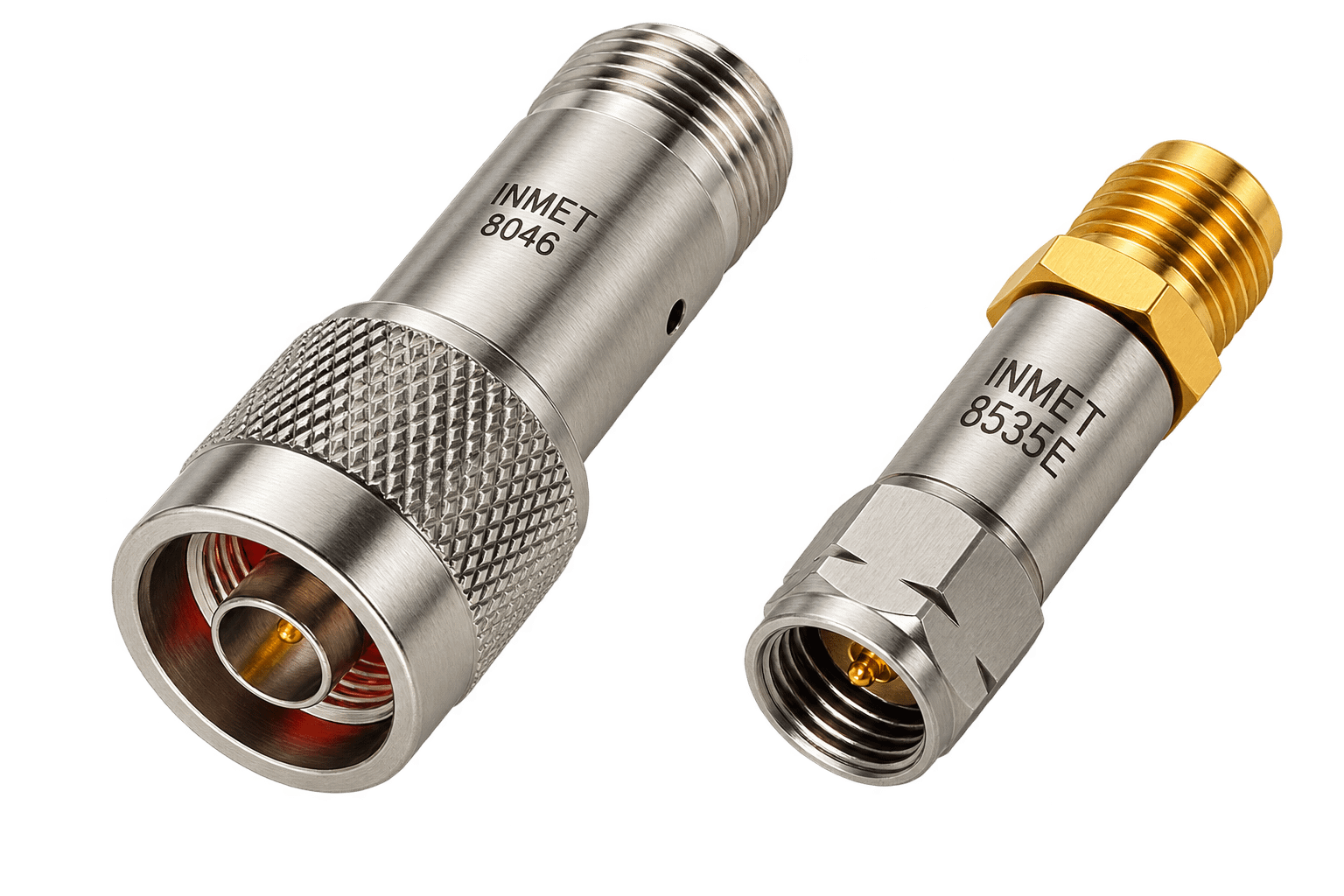
Spectrum Control Inner DC Blocks provide DC isolation on the center conductor of a coaxial transmission line while allowing RF and microwave signals to pass through. Available across a broad range of frequencies, voltage ratings, and coaxial connector configurations, these passive components provide a simple way to prevent unwanted DC from passing between interconnected RF devices.
Designed for integration into RF and microwave signal paths, Inner DC Blocks are available for applications ranging from general-purpose RF through high-frequency microwave systems. Options include SMA, 2.9 mm, and 2.4 mm interfaces, with configurations supporting frequencies as high as 50 GHz and specialized models for higher DC voltage requirements.
Inner DC Block Performance & Selection
How it Works
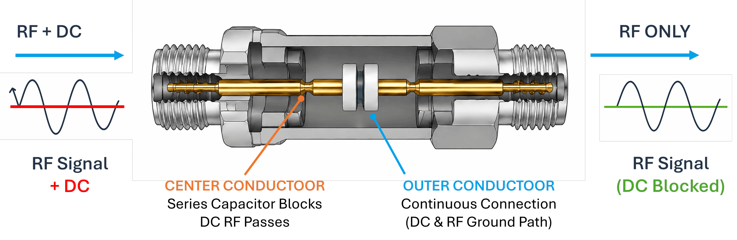
An Inner DC Block uses a series capacitor on the center conductor to block DC while allowing RF and microwave signals to pass. The outer conductor remains electrically continuous, distinguishing Inner DC Blocks from Outer and Inner/Outer designs, which isolate different parts of the coaxial transmission path.
Why it Matters
DC on an RF transmission line can interfere with connected equipment or sensitive components. An Inner DC Block provides passive isolation to help protect devices, separate bias conditions, and prevent unwanted DC from reaching test equipment while maintaining RF performance across the required frequency range.
Understanding DC Block Performance
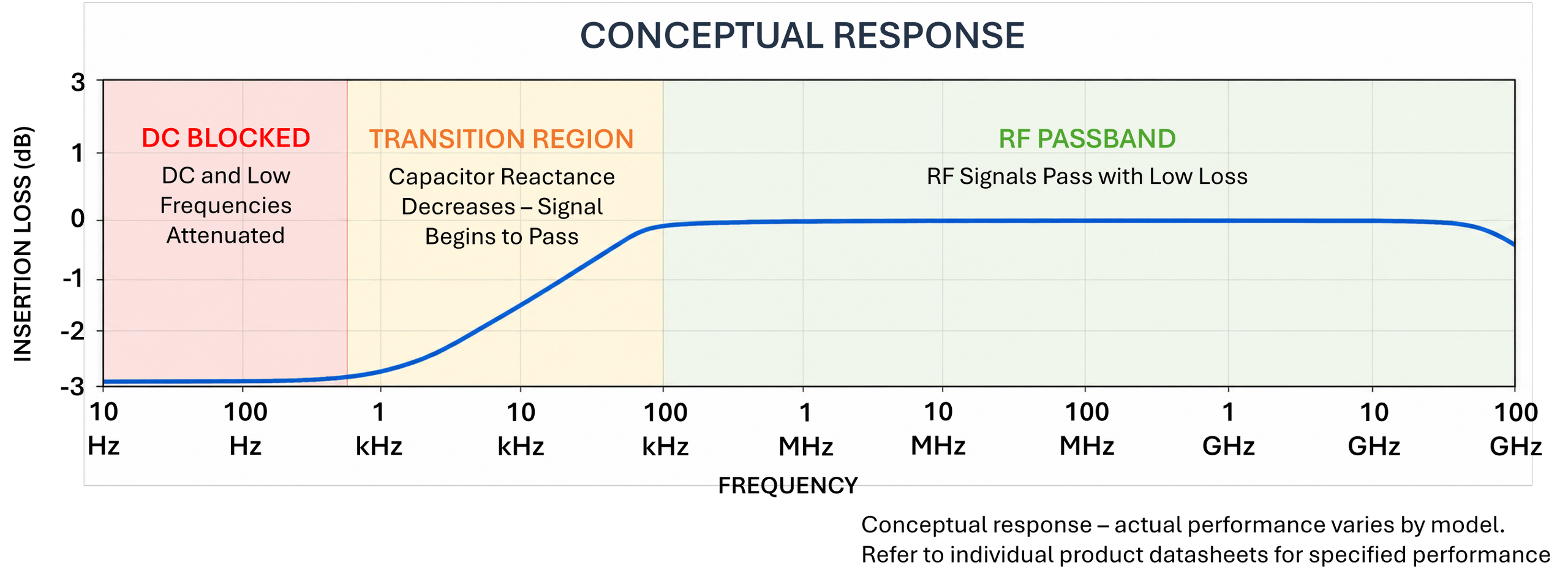
Unlike a filter designed to select a specific portion of the RF spectrum, an Inner DC Block rejects DC while providing a low-loss path for RF and microwave signals across its specified frequency range. Key performance factors include:
-
Frequency Range: Defines the frequencies the DC block can pass
-
RF Performance: Low insertion loss and VSWR help maintain signal quality and minimize reflections.
-
Voltage & Connectors: Ensure the voltage rating and connector configuration meet system requirements.
By isolating the center conductor while keeping the outer conductor continuous, an Inner DC Block prevents unwanted DC from reaching connected equipment while maintaining RF performance.
Part Number |
Freq. Range (GHz) |
Voltage |
VSWR Max. |
Insertion Loss (dB) |
Connector / Configuration |
| General Purpose | |||||
| 8037 | 0.01 - 18 | 200 | 1.35:1 | 0.5 | SMA - M/F |
| 8043 | 0.01 - 18 | 200 | 1.35:1 | 0.5 | SMA - M/M |
| 8060A | 7 kHz - 26.5 | 75 | 1.50:1 | 0.75 | 2.9mm - M/F |
| 8063A | 7 kHz - 26.5 | 75 | 1.50:1 | 0.75 | 2.9mm - F/F |
| 8066A | 7 kHz - 26.5 | 75 | 1.50:1 | 0.75 | 2.9mm - M/M |
| 8141A | 0.01 - 40 | 200 | 1.45:1 | 0.75 | 2.9mm - M/F |
| 8177 | 0.1 - 50 | 75 | 1.75:1 | 1.5 | 2.4mm - M/F |
| 8315 | 25 kHz - 20 | 100 | 1.50:1 | 0.5 | SMA M / 2.9mm F |
| 8535EF | 7 kHz - 50 | 30 | 1.65:1 | 1.25 | 2.4mm - F/F |
| 8535EM | 7 kHz - 50 | 30 | 1.65:1 | 1.25 | 2.4mm - M/M |
| AA-8046 | 0.01 - 18 | 200 | 1.35:1 | 0.6 | N-Type - M/F |
| AA-8049 | 0.01 - 18 | 200 | 1.35:1 | 0.6 | N-Type - F/F |
| AA-8052 | 0.01 - 18 | 200 | 1.35:1 | 0.6 | N-Type - M/M |
| Microminiature | |||||
| 8055H | 0.01 - 18 | 200 | 1.35:1 | 0.5 | SMA - Hex - M/F |
| AA-8055 | 0.01 - 18 | 200 | 1.35:1 | 0.5 | SMA - M/F |
| High Voltage | |||||
| 8529A | 0.01 - 4 | 900 | 1.60:1 | 1.5 | SMA - M/F |
| Broadband | |||||
| 8535E | 7 kHz - 50 | 30 | 1.65:1 | 1.25 | 2.4mm - M/F |
| 8535K | 16 kHz - 40 | 75 | 1.65:1 | 1.25 | 2.9mm - M/F |
| 8535KH | 16 kHz - 40 | 75 | 1.65:1 | 1.25 | 2.9mm - Hex - M/F |
| AA-8535 | 7 kHz - 23 | 100 | 1.35:1 | 0.75 | SMA - Hex - M/F |
Inner DC Block - How it Works
Series Capacitor Blocks DC and Passes RF
Typical Applications
-
RF test and measurement
-
Radar systems
-
Electronic warfare systems
-
SATCOM and communications equipment
-
Aerospace and defense electronics
-
RF subsystem integration
- DC bias isolation
- Protection of sensitive RF and microwave equipment
Why Choose Spectrum Control?
-
Broad selection of Inner, Outer, and Inner/Outer DC Blocks
-
Frequency coverage through 50 GHz
-
Multiple DC voltage ratings
-
SMA, 2.9 mm, 2.4 mm, and other coaxial interfaces
-
Low-loss RF and microwave designs
-
Compact, passive 50-ohm solutions
-
Multiple connector and mechanical configurations
-
Detailed electrical and mechanical specifications