

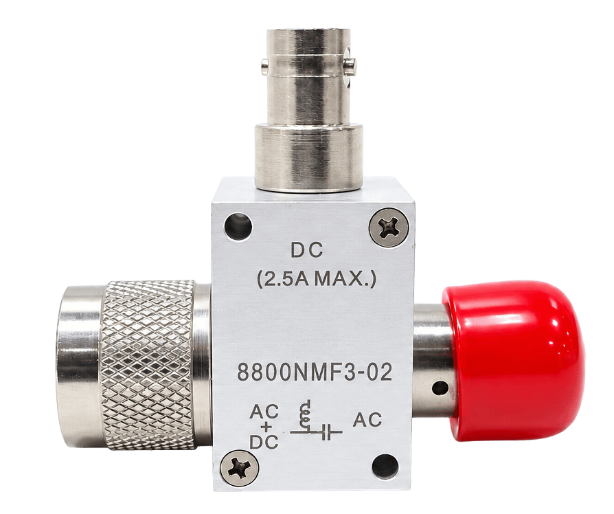
Spectrum Control bias tees with Type N connectors combine DC bias and RF signals onto a single transmission line while maintaining isolation between the DC and RF paths. Their rugged coaxial design provides a secure connection for powering active RF components without requiring a separate power cable.
Engineered for reliable broadband performance, these bias tees support frequencies up to 12 GHz, DC current up to 2.5 A, and DC voltage up to 100 V. Type N interfaces and multiple connector configurations make them well suited for antennas, amplifiers, communications equipment, radar systems, and RF test applications.
Bias Tees - Performance & Selection
Understanding Bias Tees Performance
Selecting the right Type N bias tee requires balancing RF performance with the voltage and current requirements of the connected device. The operating frequency range, signal quality, power handling, and isolation should all be considered to ensure reliable performance. Key factors include:
-
Frequency Range: Identifies the RF frequencies the bias tee can pass.
-
Insertion Loss and VSWR: Indicate how effectively signal strength is maintained and reflections are minimized.
-
DC Voltage and Current: Define the amount of power the bias path can safely deliver.
-
Isolation: Measures how effectively RF energy is prevented from entering the DC port.
Evaluating these specifications together helps ensure reliable signal transmission and DC power delivery across the intended operating range.
How it Works
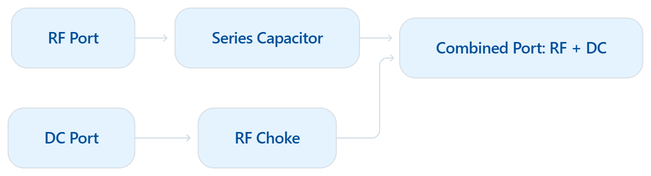
A Type N bias tee combines DC power and an RF signal through separate internal paths. An inductor directs DC to the combined port while blocking RF, and a capacitor passes the RF signal while preventing DC from reaching the RF-only port.
Why it Matters
Type N bias tees allow RF signals and DC power to share one coaxial connection, reducing cabling and simplifying system integration. Their threaded interfaces provide secure, reliable connections for RF and microwave systems.
Part Number |
Freq. Range (GHz) | Insertion Loss (dB) | Current (A) | DC Voltage | Connector Configurations |
| 8800N | 10 MHz - 12 | 0.50 - 3.00 | 2.5 | 100 max. |
M/F, M/M,
F/F, F/M
|
| 8820N | 500 MHz - 6 | 0.50 - 1.00 | 7 | 100 max. |
M/F, M/M,
F/F, F/M
|
Bias Tees - How They Work
Combining RF Signals and DC Power Through a Secure Type N Connection.
A Type N bias tee provides separate internal paths for the RF signal and DC power. A series capacitor passes the RF signal through the device while blocking DC from reaching the RF-only port.
DC power enters through the DC port and travels through an inductor, or RF choke. This path delivers DC to the combined port while limiting RF energy from traveling back toward the power source.
The RF and DC paths join at the combined port, allowing both to travel through one Type N coaxial connection. This configuration provides power to amplifiers, antennas, and other active RF components without the need for a separate power cable.
- Series capacitor: Allows RF signals to pass while blocking DC
- RF Choke: Directs DC to the combined port while blocking RF
- Combined Port: Carries RF and DC through a single Type N connection

Typical Applications
-
Base station and repeater infrastructure
-
Outdoor and remote antenna systems
-
SATCOM ground equipment
-
Radar transmit and receive systems
-
RF signal distribution networks
-
Remote receiver and amplifier powering
- Industrial wireless and telemetry systems
- RF development and production testing
Why Choose Spectrum Control?
-
Frequency coverage through 12 GHz
-
DC current ratings up to 2.5 A
-
DC voltage ratings up to 100 V
-
High RF-to-bias-port isolation
-
Low-resistance DC bias path
-
Secure Type N threaded connections
-
Multiple male and female configurations
-
Solder-post and SMA female DC input options