
PRODUCTS / COMPONENTS / FILTERS /
Cavity RF Filters
A cavity filter is a distributed element filter built around a metal cavity rather than discrete inductors and capacitors, as in a lumped element design. Because filter performance is related to the physical size of the resonators relative to the wavelength, cavity filters are typically used at frequencies where their size remains practical while offering some of the highest power handling and Q values of any RF filter topology.
Explore our Filter Customization tool to optimize your demanding filter requirements.
Spectrum Control's cavity filter designs deliver industry-leading insertion loss as low as 0.1 dB, combined with power-handling capability of up to 400 watts. This combination helps minimize signal degradation, preserve receiver sensitivity, and support reliable operation in demanding, high-power RF systems. Through careful component selection and proven design methods, our engineers apply advanced techniques, including intermod suppression, to achieve the required selectivity, rejection, and stability. These capabilities enable cavity filter solutions tailored to challenging performance requirements across a wide range of defense, aerospace, and communications applications.
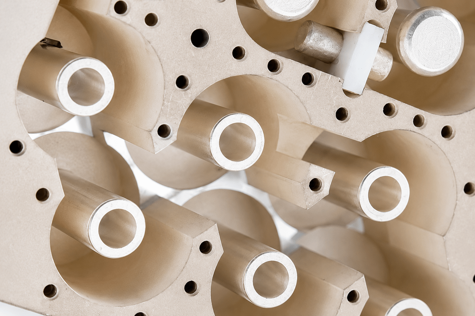
Cavity filter design advantages
 Machined from lightweight aluminum to reduce weight
Silver plating for low loss performance
Proprietary techniques to minimize temperature drift to less than 1 ppm/°C
Pseudo elliptic designs incorporate cross-coupling to create transmission zeros, improving close-in rejection without increased insertion loss
Unique resonator designs that increase peak power-handling capability
Silver-plated resonators and cavity surfaces for higher Q than lower-cost plating
Low-dielectric stabilizing structures for extreme shock and vibration
Key Performance
|
Feature
|
Specification |
|
Frequency
|
400 MHz to 40 GHz |
|
Size
|
Moderate Size |
|
Cost
|
Moderate Price |
|
Harmonics
|
Minimized spurious passbands |
|
Power Handling
|
Up to 400 Watts |
|
Insertion Loss
|
As low as 0.1 dB |
How Cavity Filters Work
Pseudo-elliptic cross-coupling
Unlike Chebyshev or Butterworth designs, in which rejection increases gradually with distance from the passband, cavity pseudo-elliptic designs use cross-coupling to force the signal toward zero at specific nearby frequencies, creating a steeper skirt between the passband and stopband while reducing the pole count needed to meet a rejection target. This also reduces size and cost.
Thermal stability through Invar
Many cavity designs use Invar for resonator and housing construction because of its very low coefficient of thermal expansion, which helps maintain a stable frequency response as the ambient temperature changes.
Faraday-cage shielding
A cavity’s solid metal housing prevents EMI from leaking out and external channel noise from leaking in, enabling attenuation levels above 100 dB, which are difficult to achieve with topologies affected by parasitic coupling.
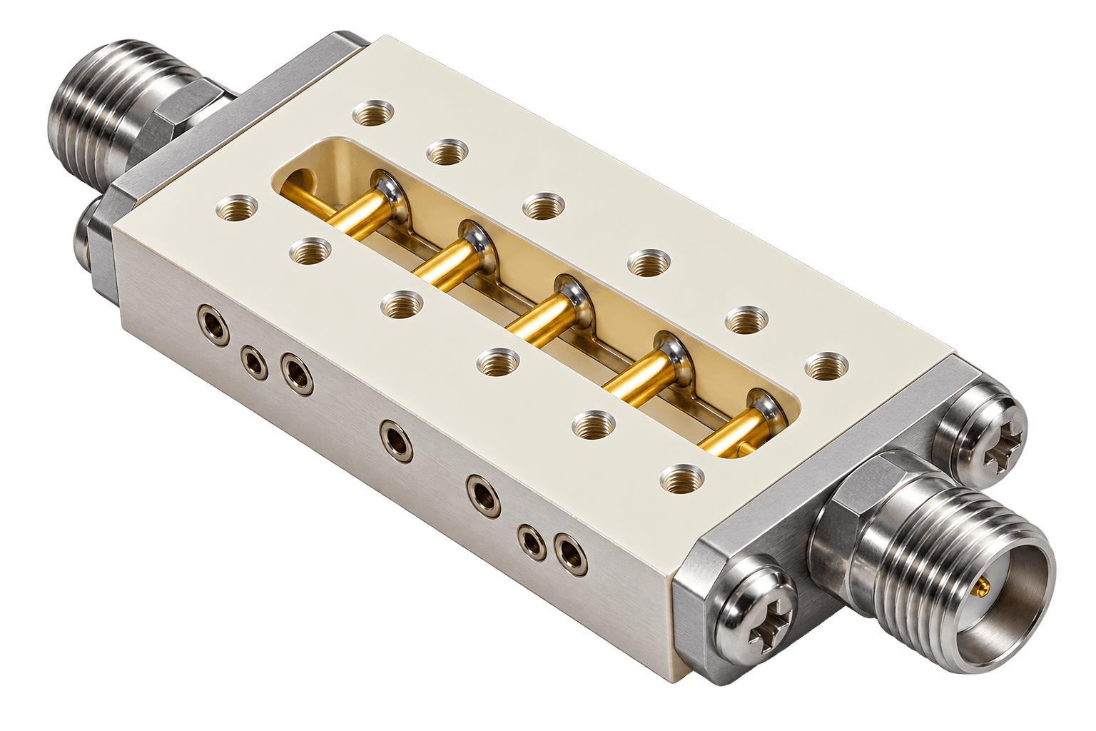
Iris coupling
Precisely shaped apertures in a cavity’s walls transfer electromagnetic energy between adjacent resonators. These apertures function as reactive shunt inductances or capacitances that shape the overall filter response and help reduce unit size.
Silver-plated resonators
Because silver has the highest electrical conductivity of any metal, plating the resonators and cavity interior with silver reduces resistive energy loss as heat. This improves signal efficiency, increases Q, and lowers insertion loss, helping the filter maintain reliable electrical performance across its operating frequency range.
Bimetallic & low-dielectric stabilizing structures
Cavity designs can incorporate bimetallic and low-dielectric stabilizing structures that reduce sensitivity to shock, vibration, and thermal drift. This stability is critical in defense and aerospace platforms, where even microscopic resonator shifts can cause frequency drift or microphonics.
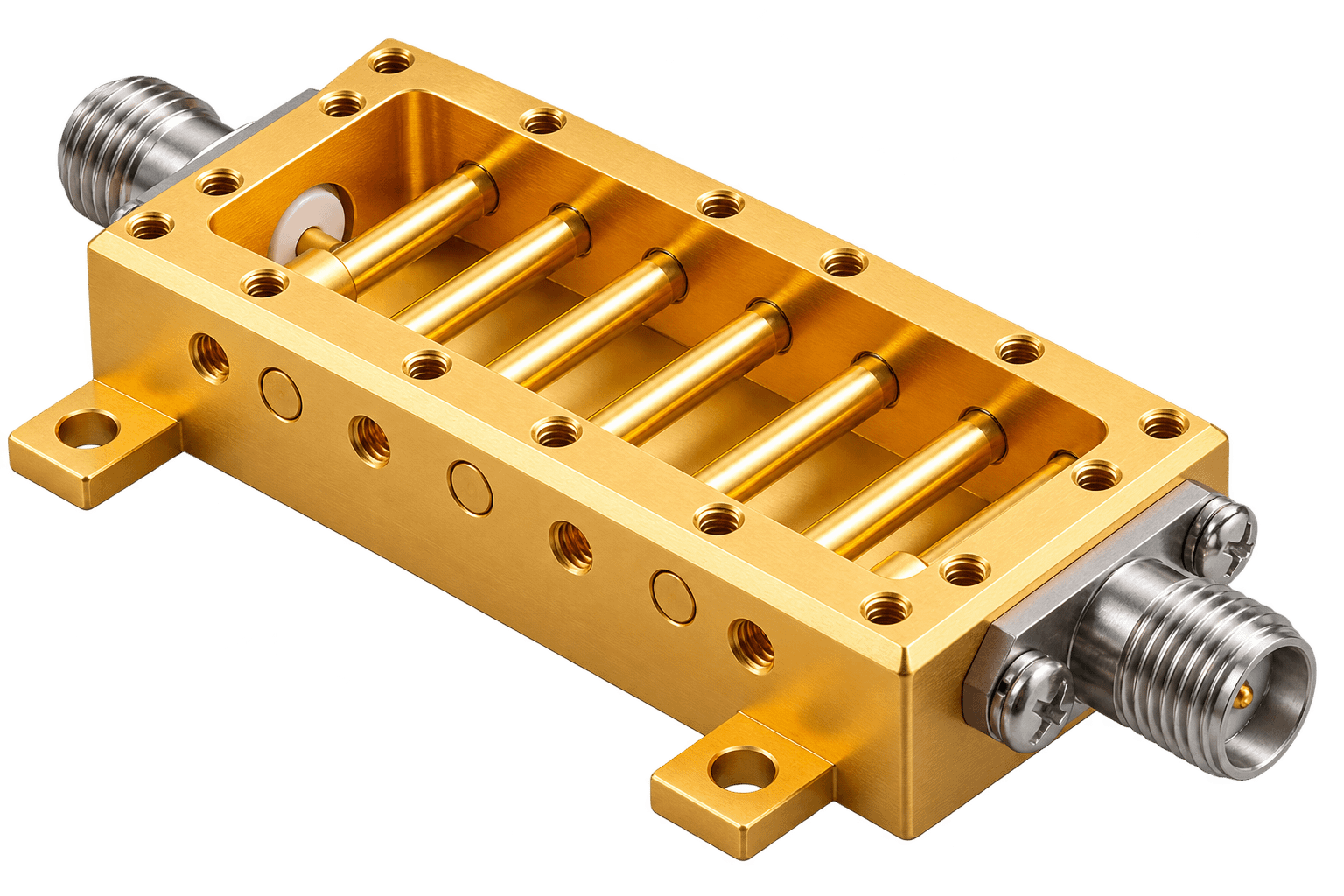
How Cavity Filters Compare to Other Topologies
|
Cavity Filters: Distributed-element designs that provide the highest power handling and Q among common filter topologies, making them well suited for demanding narrowband applications. |
|
Lumped Element: Use discrete inductors and capacitors to provide a smaller footprint below 10 GHz, along with lower cost, easier tuning, and greater design flexibility. |
|
Ceramic Filters: Use compact ceramic resonators to provide a strong balance of size, cost, and electrical performance at frequencies up to 6 GHz. |
|
SAW Filters: Use piezoelectric substrate technology with interdigital transducers to deliver steep skirt selectivity and compact size at frequencies up to 1.6 GHz for demanding RF applications. |
Applications
Defense and Radar Systems
- Minimal insertion loss
- Preferred for narrowband channel selection
- Platforms where thermal and vibration stability are mission-critical
High Power Wireless Infrastructure
- High-power base stations and repeaters
- Narrow fractional bandwidth applications requiring high Q
A Spectrum Control narrowband cavity filter centered at 2.4 GHz delivers over 100 dB rejection while handling more than 400 W, protecting sensitive receivers in high-power environments.
Available Across Filter Functions
Cavity filter construction is available across Spectrum Control's full range of filter functions:
- Bandpass Filters: Solutions for low-loss, high-rejection performance in demanding RF applications.
- Notch Filters: Solutions for low-loss performance and targeted rejection of unwanted frequencies in compact RF designs.
- Diplexers: Solutions for combining or separating two frequency bands within a single compact cavity assembly.
- Triplexers: Solutions for combining or separating three frequency bands while maintaining low insertion loss and high isolation.
-
Multiplexers: Solutions for channelizing four or more frequency bands in demanding multichannel RF systems.
Explore our Filter Customization Tool today to specify a cavity filter for your application.