RF Attenuators
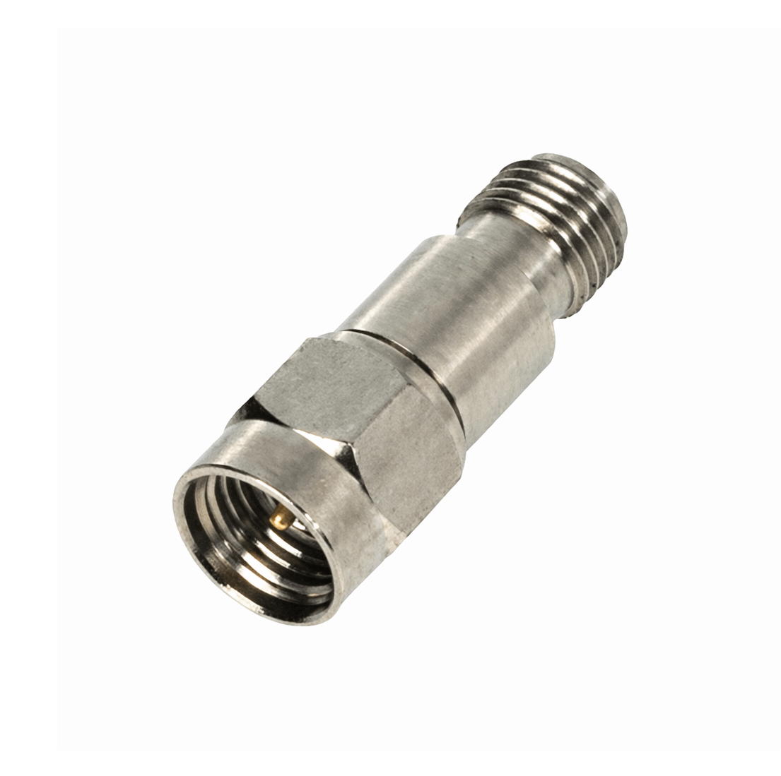
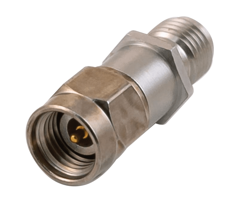
Low Power Coaxial Attenuators
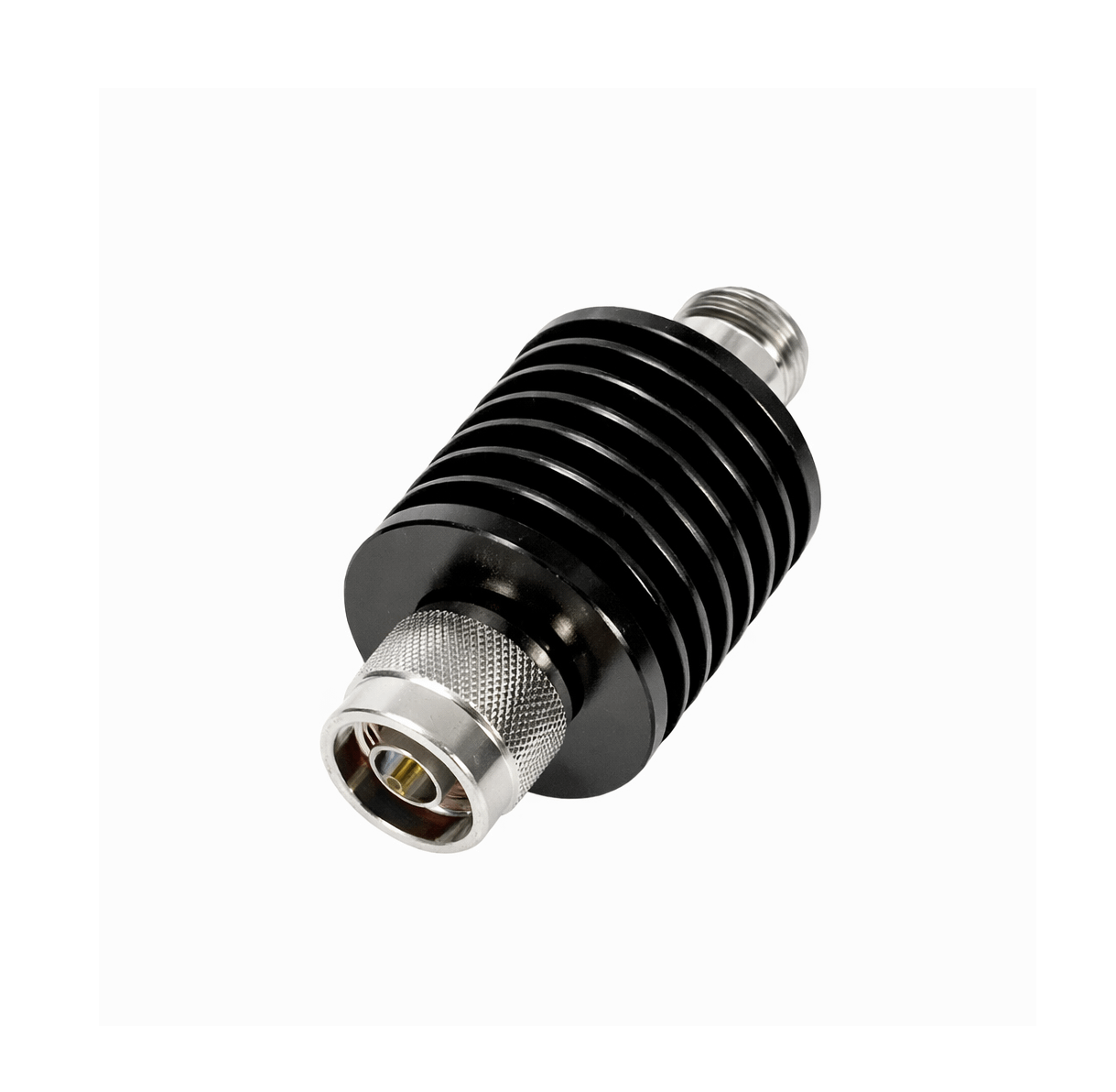
Medium Power Coaxial Attenuators
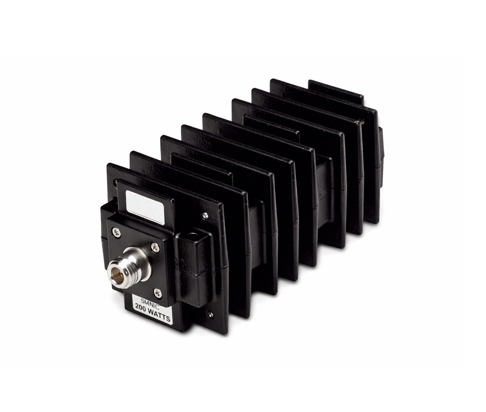
High Power Coaxial Attenuators
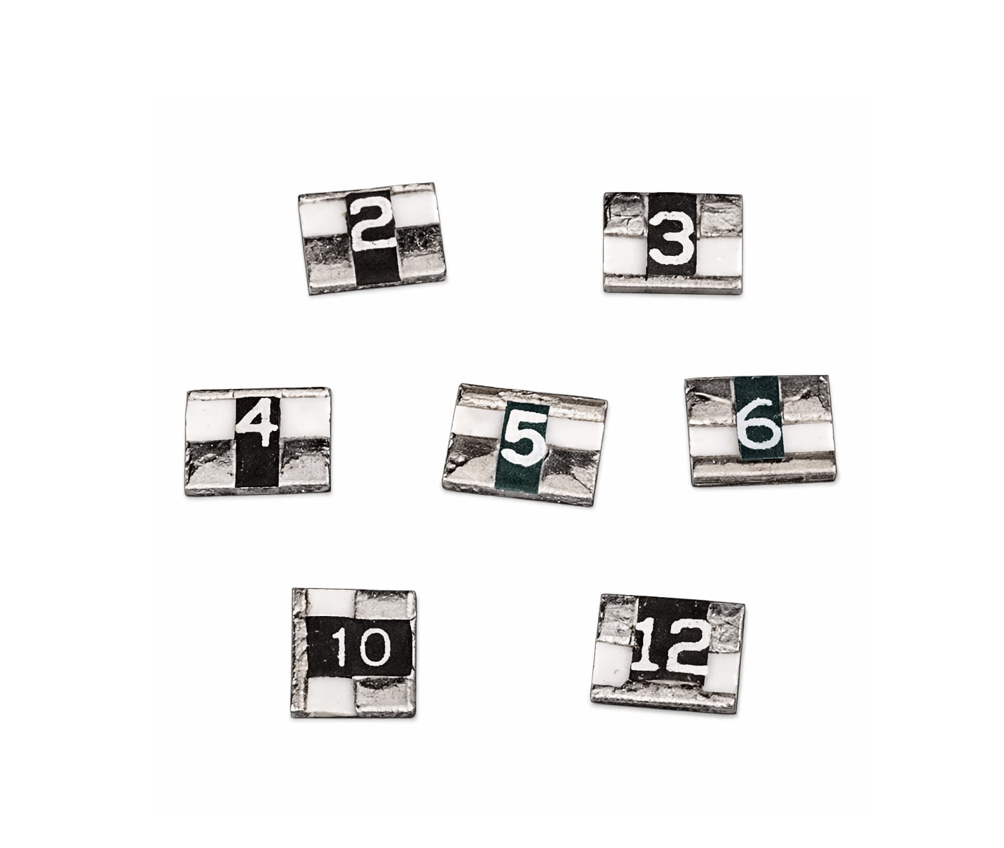
Chip Attenuators
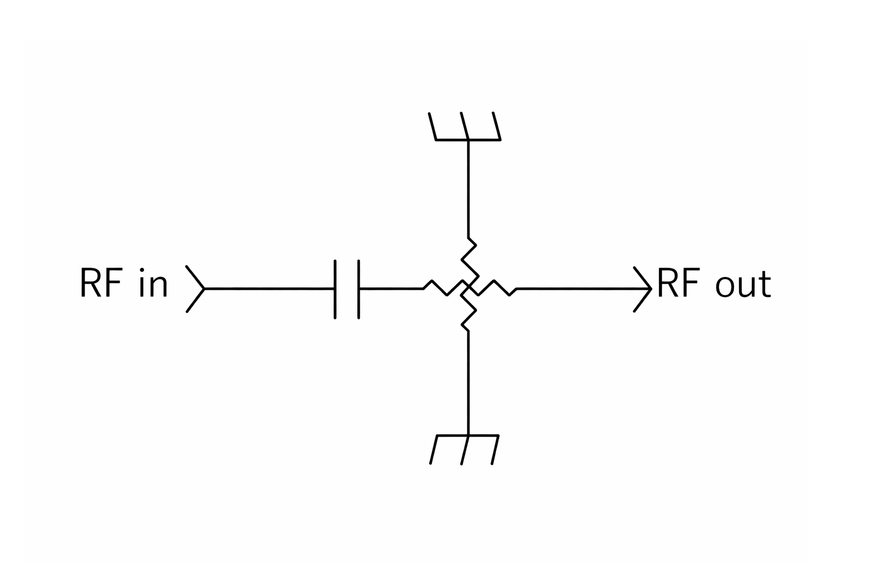
DC Blocking Attenuators
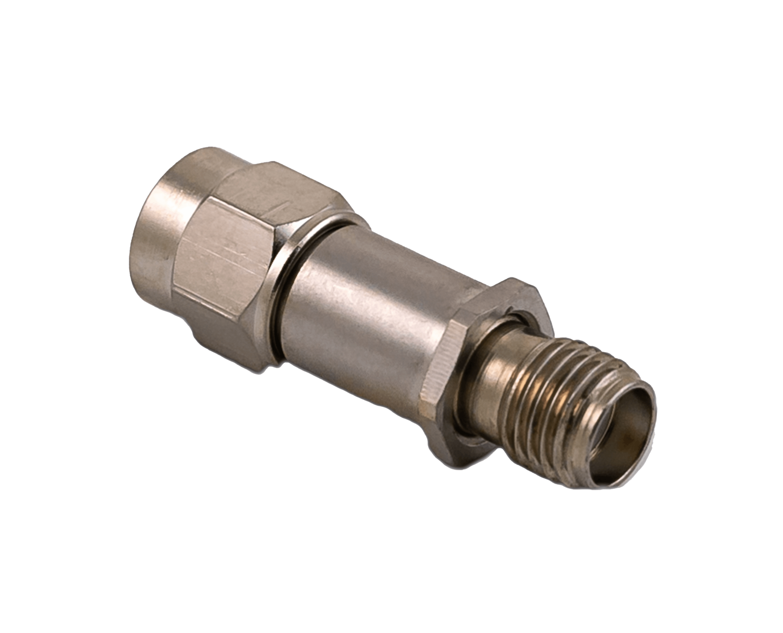
Cryo-Low Temp Coaxial Attenuators
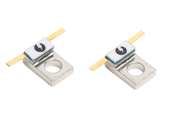
Flange Mount Attenuators
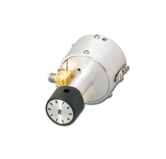
Manual Step Attenuators
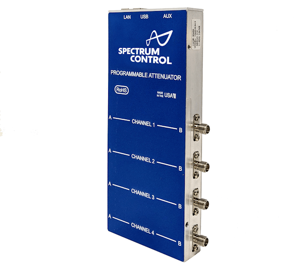
Programmable Attenuators
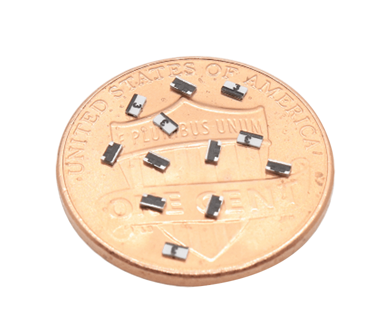
40 GHz SMT Chip Attenuator
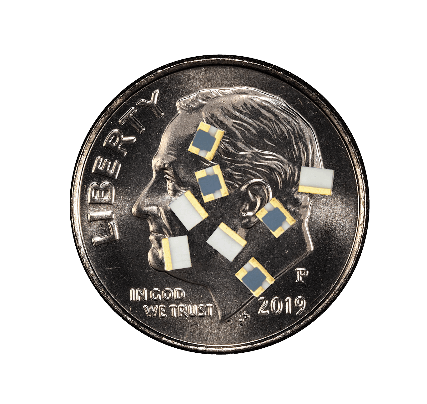
Cryo Low Temp Attenuator Chips