PRODUCTS / COMPONENTS / FILTERS /
Switched Filter Banks
Spectrum Control low loss Switched Filter Banks are loaded with standard features for demanding performance in both high-end commercial applications as well as military applications
Visit our Switched Filter Bank Customization Tool today to optimize your demanding filter requirements.
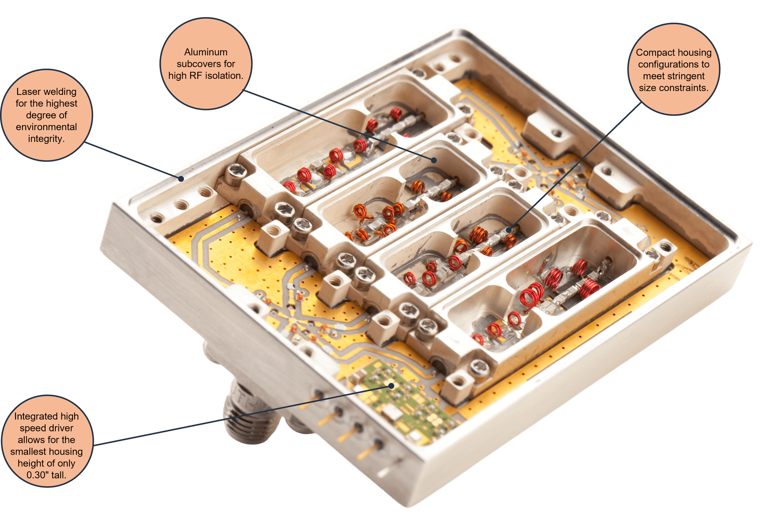
Feature rich designs are a hallmark of Spectrum’s low loss switched filter banks. Incorporating features like surge protection, integrated couplers, voltage regulators, and laser welded assembly, allows the customer to optimize for both high performance and intelligent system communication.
By using matched fast GaAs switches, Spectrum is able to meet exceptionally fast switching speeds of as low as 0.1 μs Channel-to-channel isolation performance up to 80 dB is also achieved using channelized manifolds and Aluminum subcovers.
Features include a blend of both standard and custom options:
- Input voltage regulators
- TTL or CMOS controls
- Input DC and RF surge protection
- FET or PIN diode switching
- Temperature compensating circuitry
- Integrated couplers support
- Input signal injection port
- Hermetic laser welding
Loaded with Standard Features
High Performance is not the only facet of Spectrum Control's industry leading Switched Filter Banks. Another important element that sets us apart is features. Loaded with standard features, our proven designs are engineered for demanding performance in both high-end commercial applications as well as military markets.
Channelized Manifolds: Switch manifolds are channelized to obtain maximum channel-to-channel isolation.
Multiple Control Interfaces: We incorporate multiple interface options from TTL and CMOS to RS-232, utilizing EMI pins, and D-Sub and connectors.
| Part Number | Low Frequency | High Frequency | Insertion Loss (dB) | VSWR | Ultimate Rejection (dBc) | Switching Speed (μs) | Control Method | Power Supply (VDC/current) |
2 Channel |
||||||||
| 310-020003-002 | 80 MHz | 500 MHz | 2.0 | 1.5:1 | 60 | 0.15 | TTL | +5 V/1 mA |
| 310-020562-002 | 100 MHz | 200 MHz | 2.0 | 1.5:1 | 40 | 0.7 | TTL | +5 V/60 mA, 12 V/40 mA |
| 310-020226-002 | 300 MHz | 600 MHz | 7.0 | 1.8:1 | 60 | 0.2 | TTL | +5 V/1.5 mA |
| 310-020571-002 | 300 MHz | 1200 MHz | 2.0 | 1.5:1 | 63 | 0.7 | TTL | +5 V/60 mA, 12 V/40 mA |
| 310-020372-002 | 950 MHz | 1050 MHz | 7.0 | 1.7:1 | 70 | 0.4 | TTL | +5 V/100 mA, 15 V/40 mA |
| 310-020563-002 | 1.5 GHz | 2.0 GHz | 6.5 | 1.7:1 | 80 | 0.1 | TTL | +5 V/50 mA , 5.2 V/50 mA |
| 310-020566-002 | 2.0 GHz | 2.5 GHz | 6.5 | 1.7:1 | 80 | 0.1 | TTL | +5 V/50 mA, 5.2 V/50 mA |
| 310-020626-002 | 3.5 GHz | 4.5 GHz | 5.5 | 1.5:1 | 80 | 1.0 | TTL | +5 V/75 mA |
| 310-020627-002 | 3.6 GHz | 4.4 GHz | 4.0 | 1.5:1 | 75 | 1.0 | TTL | +5 V/75 mA |
| 310-020390-002 | 4.2 GHz | 4.7 GHz | 10.0 | 2.0:1 | 60 | 0.1 | TTL | +5 V/50 mA |
| 310-020650-002 | 5.0 GHz | 6.5 GHz | 4.5 | 2.0:1 | 60 | 0.5 | TTL | +5 V/100 mA, 5 V/40 mA |
3 Channel |
||||||||
| 310-020021-003 | 500 MHz | 550 MHz | 7.0 | 1.5:1 | 70 | 0.22 | TTL | +5 V/75 mA |
| 310-020410-002 | 550 MHz | 600 MHz | 6.0 | 1.5:1 | 60 | 0.15 | TTL | +12 V/100 mA |
| 310-020393-002 | 750 MHz | 1250 MHz | 4.0 | 1.7:1 | 60 | 0.4 | TTL | +5 V/250 mA, 15 V/100 mA |
| 310-020405-002 | 1.75 GHz | 8.25 GHz | 5.0 | 2.5:1 | 55 | 0.4 | TTL | +5 V/100 mA, 12 V/40 mA |
| 310-020137-002 | 2.4 GHz | 6.0 GHz | 5.0 | 2.0:1 | 50 | 1.0 | TTL | +5 V/80 mA, 5 V/30 mA |
| 310-020342-002 | 3.5 GHz | 4.0 GHz | 5.0 | 1.5:1 | 80 | 0.3 | TTL | +5 V/125 mA, 15 V/70 mA |
4 Channel |
||||||||
| 310-020421-002 | DC | 20 MHz | 2.5 | 1.5:1 | 80 | 0.4 | TTL | +5 V/30 mA |
| 310-020440-002 | 50 MHz | 90 MHz | 9.0 | 1.7:1 | 30 | 0.4 | TTL | +5 V/100 mA, 5 V/50 mA |
| 310-020136-006 | 130 MHz | 190 MHz | 9.0 | 1.7:1 | 50 | 0.4 | TTL | +5 V/100 mA, 5 V/50 mA |
| 310-020295-002 | 700 MHz | 850 MHz | 3.0 | 1.5:1 | 60 | 0.5 | TTL | +5 V/75 mA, 12 V/75 mA |
| 310-020296-002 | 750 MHz | 1000 MHz | 3.0 | 1.5:1 | 60 | 0.5 | TTL | +5 V/75 mA, 12 V/75 mA |
| 310-020297-002 | 800 MHz | 1100 MHz | 4.0 | 1.5:1 | 60 | 0.5 | TTL | +5 V/75 mA, 12 V/75 mA |
| 310-020298-002 | 850 MHz | 1200 MHz | 4.0 | 1.5:1 | 60 | 0.5 | TTL | +5 V/75 mA, 12 V/75 mA |
| 310-020634-002 | 1.9 GHz | 6.1 GHz | 4.0 | 1.8:1 | 60 | 0.5 | TTL | +5 V/100 mA, 5 V/50 mA |
| 310-020635-002 | 10 GHz | 13 GHz | 5.2 | 1.8:1 | 60 | 0.5 | TTL | +5 V/100 mA, 5 V/50 mA |
5 Channel |
||||||||
| 310-020448-002 | 40 MHz | 90 MHz | 9.5 | 1.5:1 | 60 | 0.2 | TTL | +5 V/20 mA |
| 310-020460-002 | 90 MHz | 140 MHz | 10.0 | 1.5:1 | 60 | 0.2 | TTL | +5 V/20 mA |
| 310-020434-002 | 140 MHz | 180 MHz | 10.5 | 1.5:1 | 60 | 0.2 | TTL | +5 V/20 mA |
| 310-020441-002 | 150 MHz | 650 MHz | 6.5 | 1.5:1 | 60 | 0.2 | TTL | +5 V/20 mA |
| 310-020543-002 | 150 MHz | 1600 MHz | 12.0 | 2.0:1 | 60 | 0.2 | TTL | +5 V/20 mA |
| 310-020012-002 | 500 MHz | 1500 MHz | 6.0 | 1.5:1 | 60 | 0.2 | TTL | +5 V/100 mA |
| 310-020227-002 | 1.0 GHz | 2.5 GHz | 3.0 | 1.8:1 | 50 | 0.4 | TTL | +5 V/150 mA, 5 V/1.5 mA |
| 310-020340-002 | 1.05 GHz | 1.45 GHz | 5.0 | 1.5:1 | 80 | 0.3 | TTL | +5 V/160 mA, 15 V/70 mA |
| 310-020341-002 | 3.85 GHz | 4.3 GHz | 5.0 | 1.5:1 | 80 | 0.3 | TTL | +5 V/160 mA, 15 V/70 mA |
| 310-020454-002 | 6.0 GHz | 20 GHz | 7.0 | 2.0:1 | 70 | 0.4 | TTL | +5 V/150 mA, 5 V/80 mA |
| 310-020032-002 | 10 GHz | 15 GHz | 6.0 | 2.0:1 | 60 | 1.2 | TTL | +15 V/160 mA, 15 V/75 mA |
6 Channel |
||||||||
| 310-020026-002 | 1.0 GHz | 8.0 GHz | 5.5 | 2.0:1 | 50 | 0.2 | TTL | +5 V/150 mA |
| 310-020641-002 | 20 MHz | 6000 MHz | 5.0 | 1.8:1 | 60 | 0.5 | TTL | +5 V/300 mA, 5 V/100 mA |
7 Channel |
||||||||
| 310-020578-002 | 20 MHz | 500 MHz | 4.0 | 1.5:1 | 60 | 10.0 | TTL | +5 V/250 mA, 15 V/125 mA |
| 310-020037-002 | 60 MHz | 6400 MHz | 6.0 | 2.0:1 | 70 | 0.4 | TTL | +5 V/280 mA, 5V/80 mA |
| 310-020481-002 | 100 MHz | 8000 MHz | 7.0 | 2.5:1 | 65 | 0.4 | TTL | +5 V/150 mA, 15 V/60 mA |
| 310-020486-002 | 0.1 GHz | 18 GHz | 7.0 | 2.5:1 | 65 | 0.4 | TTL | +5 V/190 mA, 12 V/60 mA |
| 310-020473-002 | 150 MHz | 6400 MHz | 9.0 | 2.0:1 | 70 | 0.2 | TTL | +5 V/160 mA, 5 V/60 mA |
| 310-020299-002 | 200 MHz | 2000 MHz | 6.0 | 1.5:1 | 40 | - | RS-232 | +12 V/300 mA |
| 310-020642-002 | 0.20 GHz | 20 GHz | 5.5 | 2.0:1 | 60 | 0.5 | TTL | +5 V/300 mA, 5 V/100 mA |
| 310-020497-002 | 250 MHz | 8300 MHz | 6.0 | 2.5:1 | 65 | 1.0 | TTL | +5 V/190 mA, 12 V/60 mA |
| 310-020027-002 | 500 MHz | 900 MHz | 5.5 | 1.5:1 | 80 | 1.0 | TTL | +5 V/75 mA |
| 310-020495-002 | 500 MHz | 8000 MHz | 6.0 | 2.0:1 | 65 | 1.0 | TTL | +5 V/150 mA, 12 V/75 mA |
| 310-020038-002 | 6.0 GHz | 20.25 GHz | 7.0 | 2.0:1 | 70 | 0.4 | TTL | +5 V/300 mA, 5 V/80 mA |
| 310-020496-002 | 7.4 GHz | 19.1 GHz | 8.0 | 2.5:1 | 65 | 0.4 | TTL | 5 V/150 mA, 15 V/60 mA |
8 Channel |
||||||||
| 310-020008-002 | 20 MHz | 1200 MHz | 4.5 | 2.0:1 | 50 | 1.0 | TTL | +5 V/40 mA |
| 310-020484-002 | 20 MHz | 2000 MHz | 4.0 | 2.0:1 | 60 | 1.0 | TTL | +15 V/250 mA, 15V/150 mA |
| 310-020516-002 | 20 MHz | 2000 MHz | 4.0 | 2.0:1 | 60 | 1.0 | TTL | +15 V/250 mA, 15 V/150 mA |
| 310-020507-002 | 20 MHz | 2800 MHz | 9.0 | 2.0:1 | 55 | 0.3 | TTL | +5 V/40 mA |
| 310-020525-002 | 750 MHz | 6000 MHz | 7.6 | 1.5:1 | 60 | 1.0 | TTL | +5 V/225 mA, 5 V/100 mA |
9 Channel |
||||||||
| 310-020022-003 | 20 MHz | 500 MHz | 5.0 | 2.0:1 | 50 | 0.3 | TTL | +3 V/15 mA |
10 Channel |
||||||||
| 310-020361-002 | 20 MHz | 1000 MHz | 3.5 | 2.0:1 | 50 | 10.0 | TTL | +5 V/300 mA, 12 V/150 mA |
| 310-020033-002 | 1.25 GHz | 1.35 GHz | 14.0 | 2.0:1 | 65 | 0.5 | TTL | +5 V/1.2 A, 15 V/200 mA |
| 310-020649-002 | 2.0 GHz | 20 GHz | 7.0 | 2.0:1 | 60 | 0.5 | TTL | +5 V/600 mA, 5 V/100 mA |
14 Channel |
||||||||
| 310-020619-002 | 2.9 GHz | 3.1 GHz | 14.0 | 2.0:1 | 65 | 2.5 | TTL | +5 V/600 mA |
Our key manufacturing facilities also incorporate strategic disciplined processes including APQP (Advanced Product Quality Planning) to
ensure that a specific, structured sequence of operations is completed to prevent potential quality problems.
Examples of the kinds of techniques that Spectrum Control engineers build into every filter:
-
Spring-loaded, self-locking tuning bushings and rotors reducing the risk of metallic slivers which can lead to premature failure in cavity designs.
- Annealing of all inductors to remove any metal stress memory for consistent and reliable inductor performance.
- Designs incorporating smooth angles and edges for superior plating adhesion and higher operating power.
Close Process Monitoring: We monitor critical phases of the production process with proprietary data logging technology.
World Class Quality: The efficiencies gained from our manufacturing procedures enable us to produce small volume custom products and high run requirements. We also monitor critical phases of the production process with automated SPC data measurement tools.
Preventing Problems: Spectrum Control utilizes the latest in systematic failure process controls including FMEA (Failure Mode & Effects Analysis) which is one of our primary risk mitigation tools and prevention strategies.
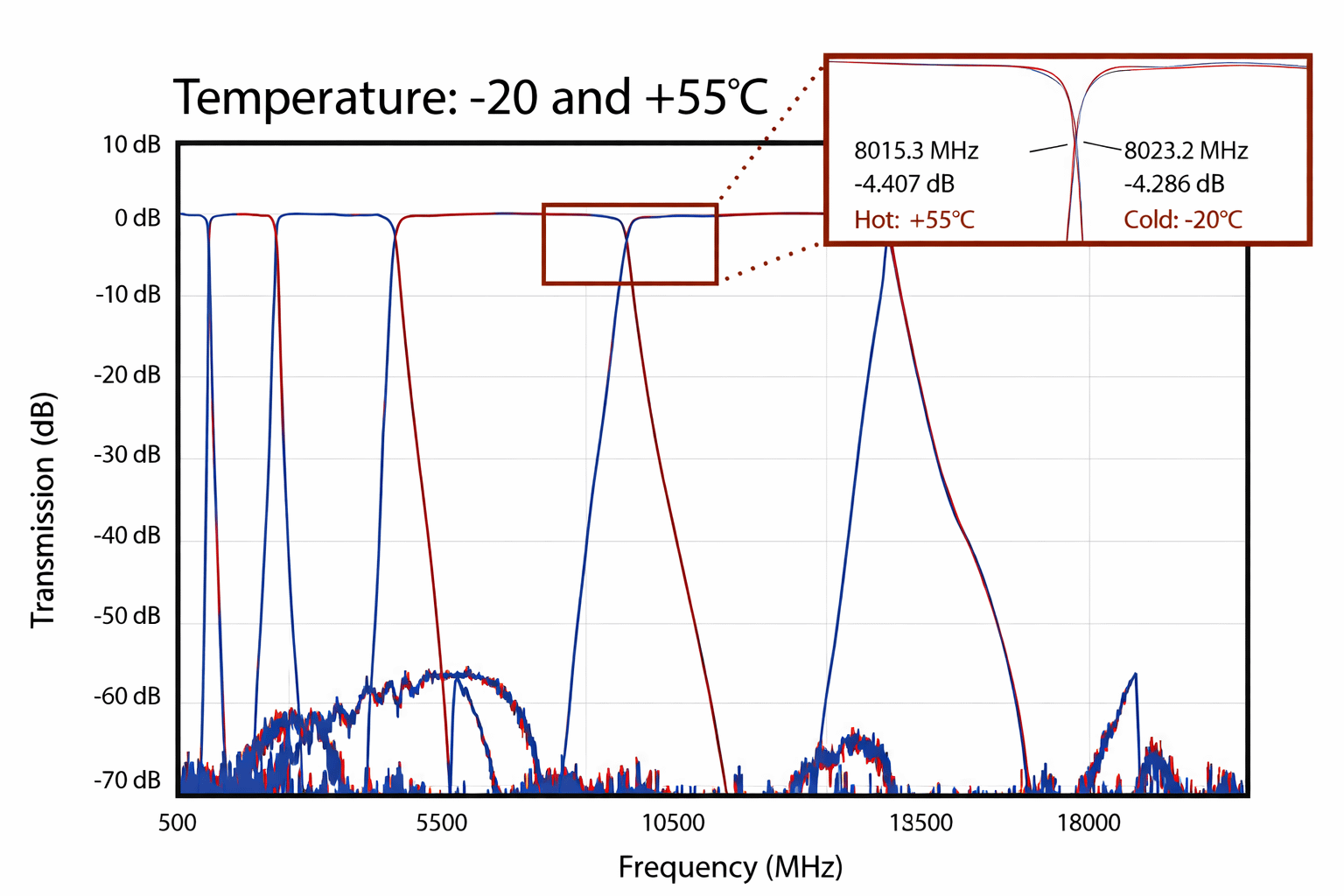
Spectrum Control's proprietary temperature stability methods deliver exceptional crossover frequency drift and temperature variation performance. Typical crossover drift can be as little as +/- 0.105 MHz/°C.
Spectrum Control offers multiple configurations and combinations:
- 2n switched channel combinations (n=number of channels)
- Switching notches
- Any combination of notches and passbands
- Switching contiguous bands
State-of-the-Art Engineering
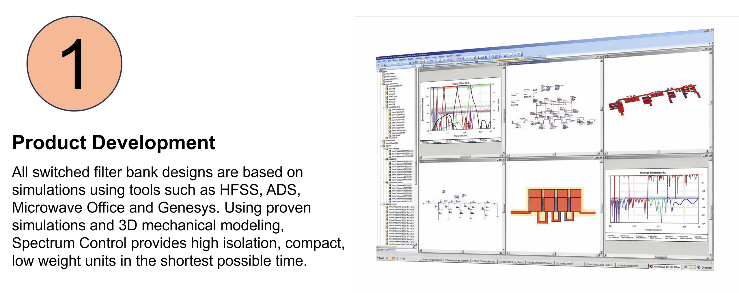
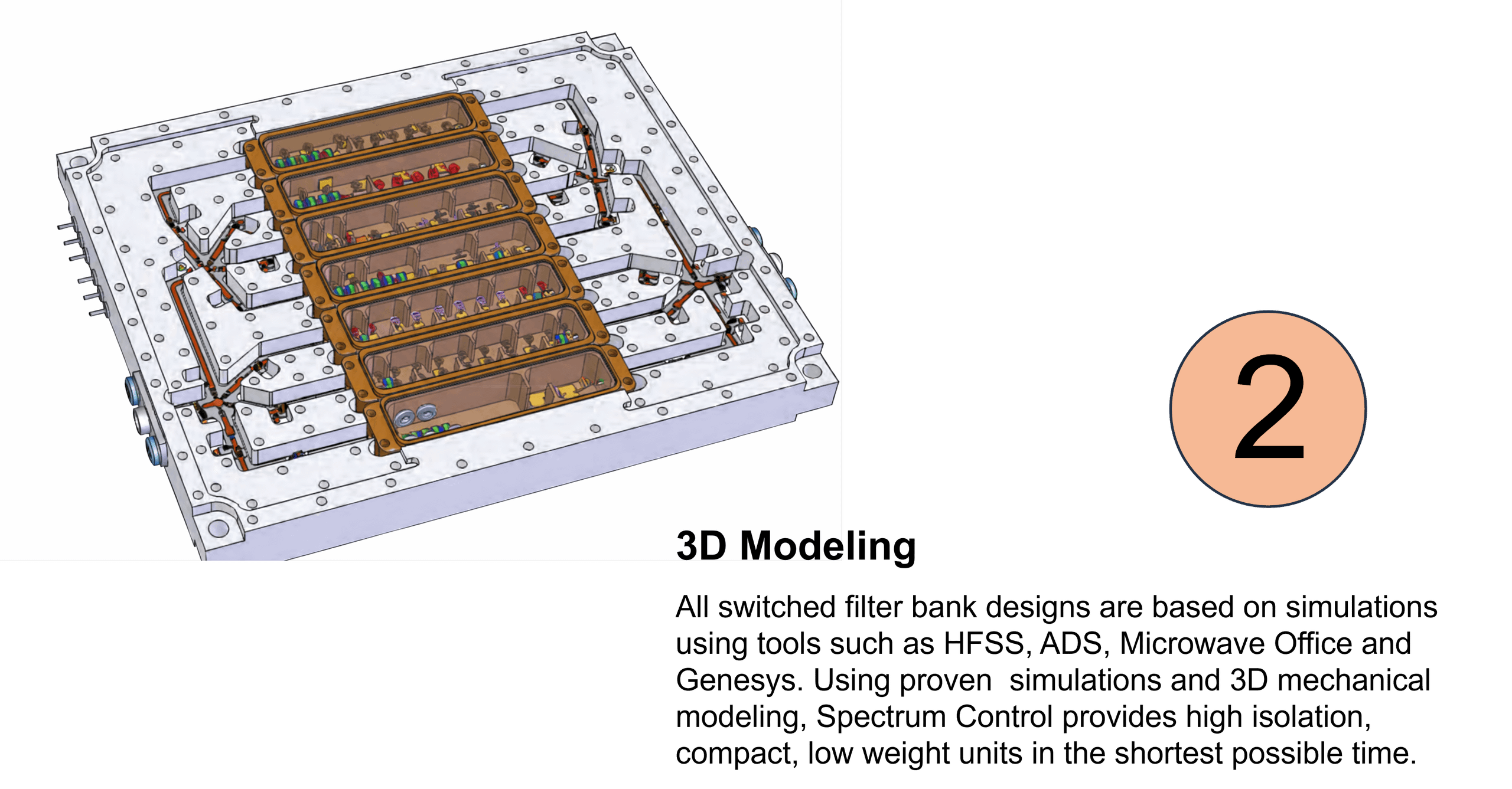
Using state-of-the-art software and simulation tools, our experienced engineering team is able to quickly take a requirement from concept to production. Utilizing these sophisticated tools sets our company apart from other firms, making API the supplier of choice for all of your switched filter bank needs.
Tools and software our RF Engineers routinely use:
- Ansoft HFSS
- Microwave Office
- Agilent ADS Design Suite
- SolidWorks
- Labview
- Agilent Genesys
- AutoCAD
- Cadence Allegro
- Ansoft Designer
- Sonnet EM Simulator