PRODUCTS / COMPONENTS / FILTERS /
Bandpass Filters
Low insertion loss bandpass filters (0.1 dB) are essential for many of today’s defense platforms and modern wireless environments that require high spectral fidelity. Low insertion loss bandpass filters (0.1 dB) by Spectrum Control help receivers detect and process low-power targets, as well as discern targets of interest in interference-heavy environments. Spectrum Control offers leading low loss bandpass filters (as noted in Microwave Journal) to help identify weak communication transmissions and recognize valuable intelligence signals in a crowded spectrum.
Visit Spectrum Control's Bandpass Filter Customization Tool today to optimize your demanding filter requirements.
Spectrum Control's database of low-loss bandpass filter designs help eliminate the need for additional gain when Size, Weight, and Power (SWaP) initiatives are in place. Low-loss filters from Spectrum Control also help suppress harmonics at the receiver front end when complex pulse or chirp signals are cascaded in the receive-side chain. This is especially critical where a flat amplitude response helps prevent distortion and unwanted spurious modulation.
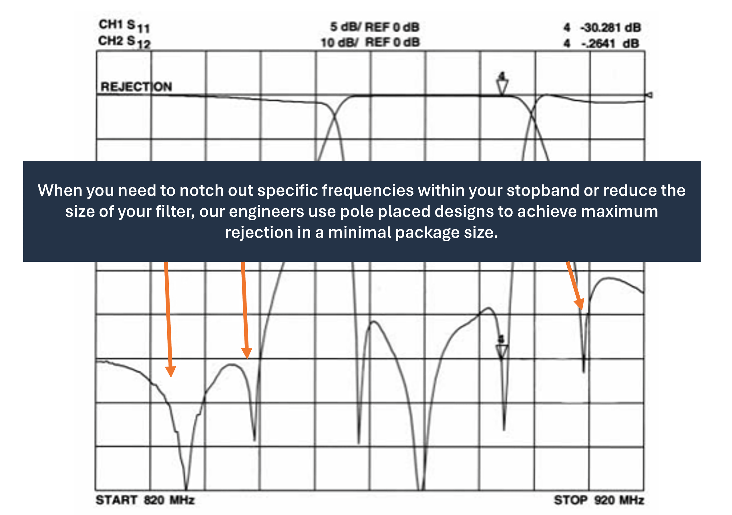
Spectrum Control’s line of low-loss bandpass filter designs (0.1 dB) delivers insertion loss as low as 0.1 dB while optimizing pole-placement strategies to achieve high rejection in a compact design. These low-loss bandpass filters (0.1 dB) also help maintain receiver sensitivity in crowded wireless spectra. High insertion loss can lead to excessive heat, requiring additional cooling strategies or heavier metal packaging to prevent thermal runaway.
Low-loss bandpass filters from Spectrum Control improve signal-to-noise ratio (SNR) performance by providing a lower-loss path for weak signals, maintaining spectral purity without harmful bit-error-rate (BER) degradation. Spectrum Control also offers a selection of Rapid Filter options, providing bandpass filters in both Chebyshev and Elliptic functions to meet critical demand requirements.
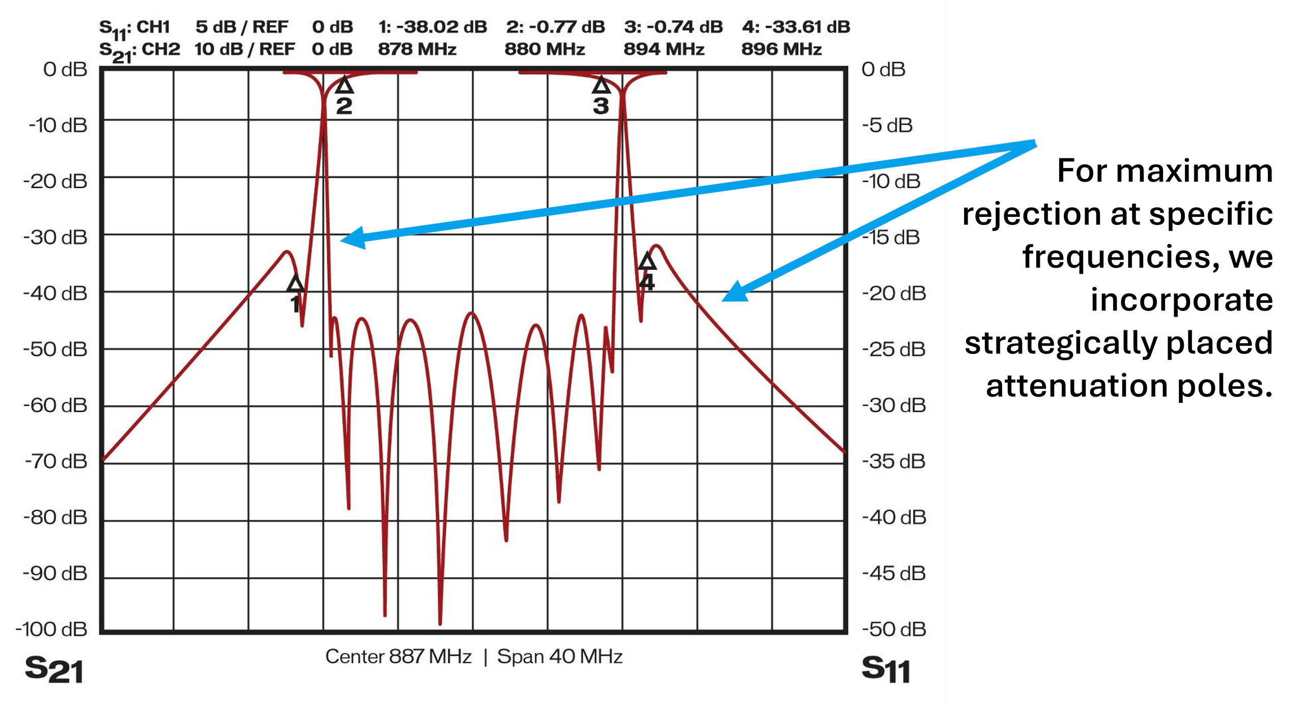
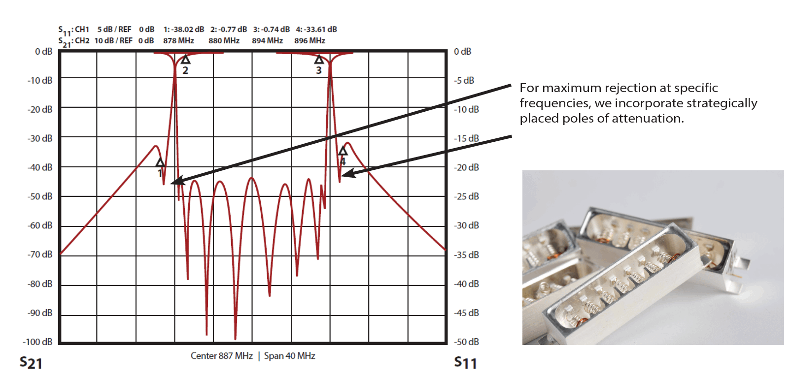
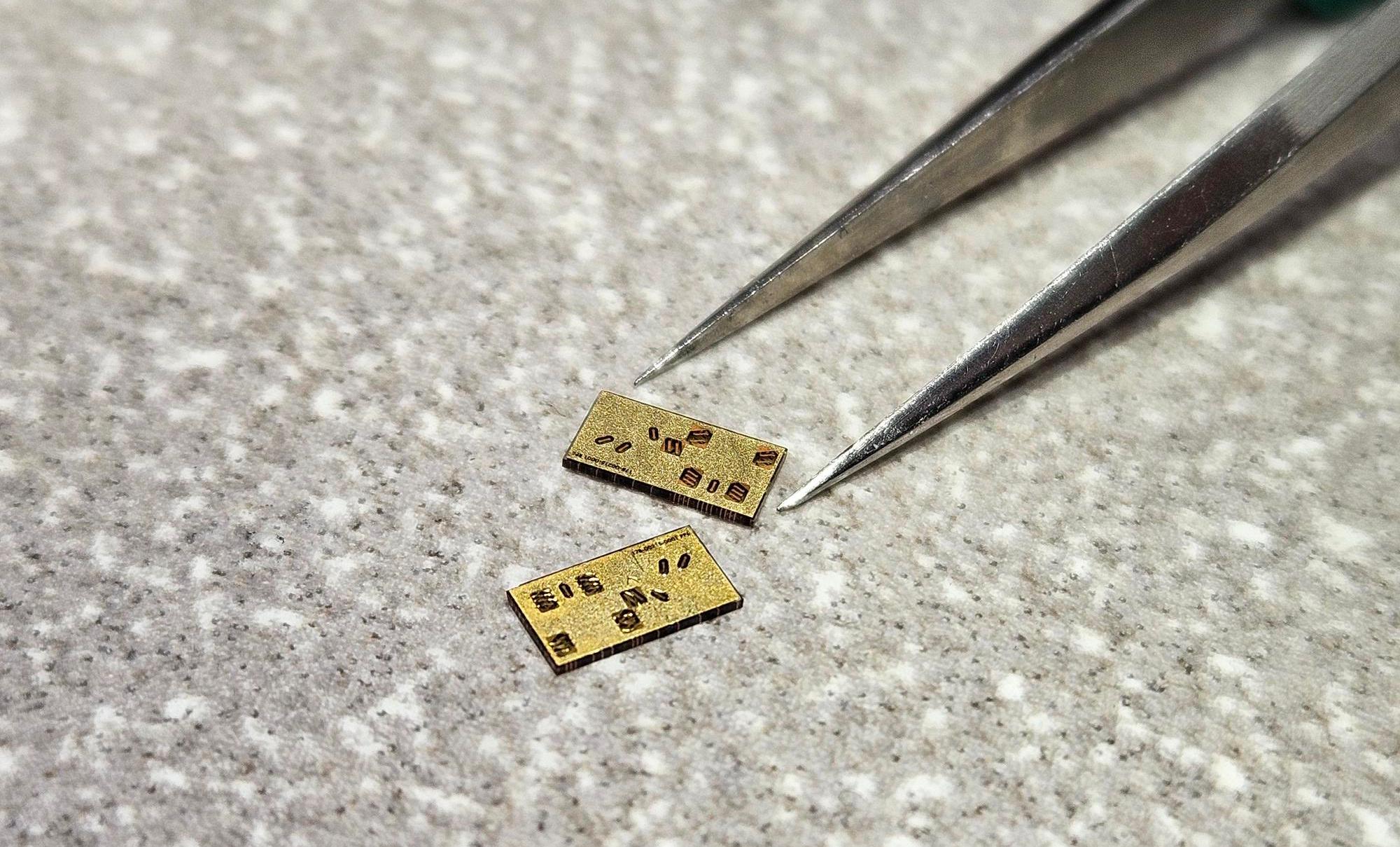
Bandpass filter frequency response
Lumped Element Low Pass Filters
Spectrum Control’s superior low-loss (0.1 dB) lumped element lowpass filters are ideal for applications where size and weight are critical. Our filter engineers are experts in lumped element design techniques and employ a range of innovative methods to meet today’s demanding specifications.
- Lightweight surface-mount packages for airborne applications
- Silver plating to reduce insertion loss
- Integral shielding for improved isolation
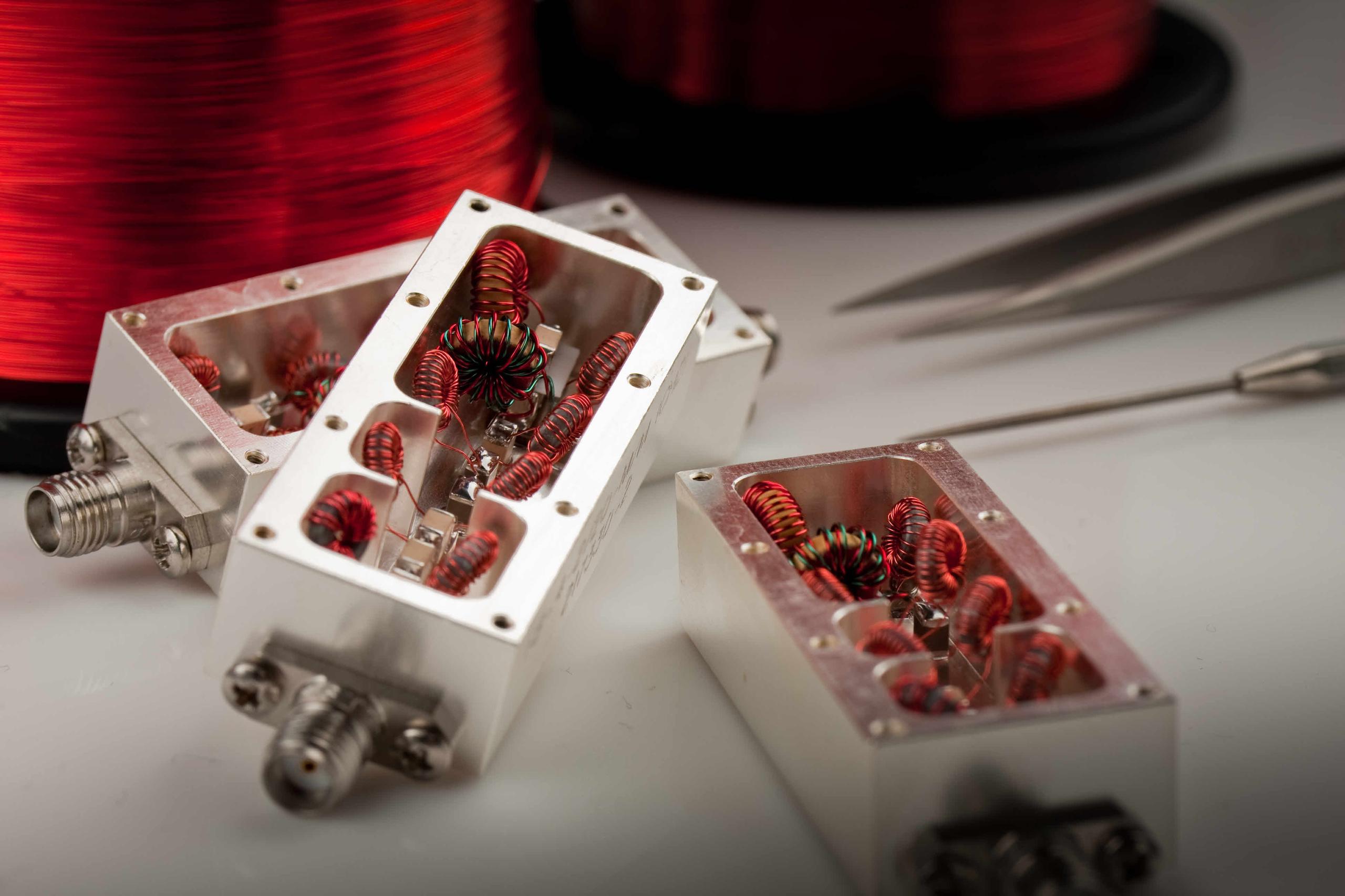
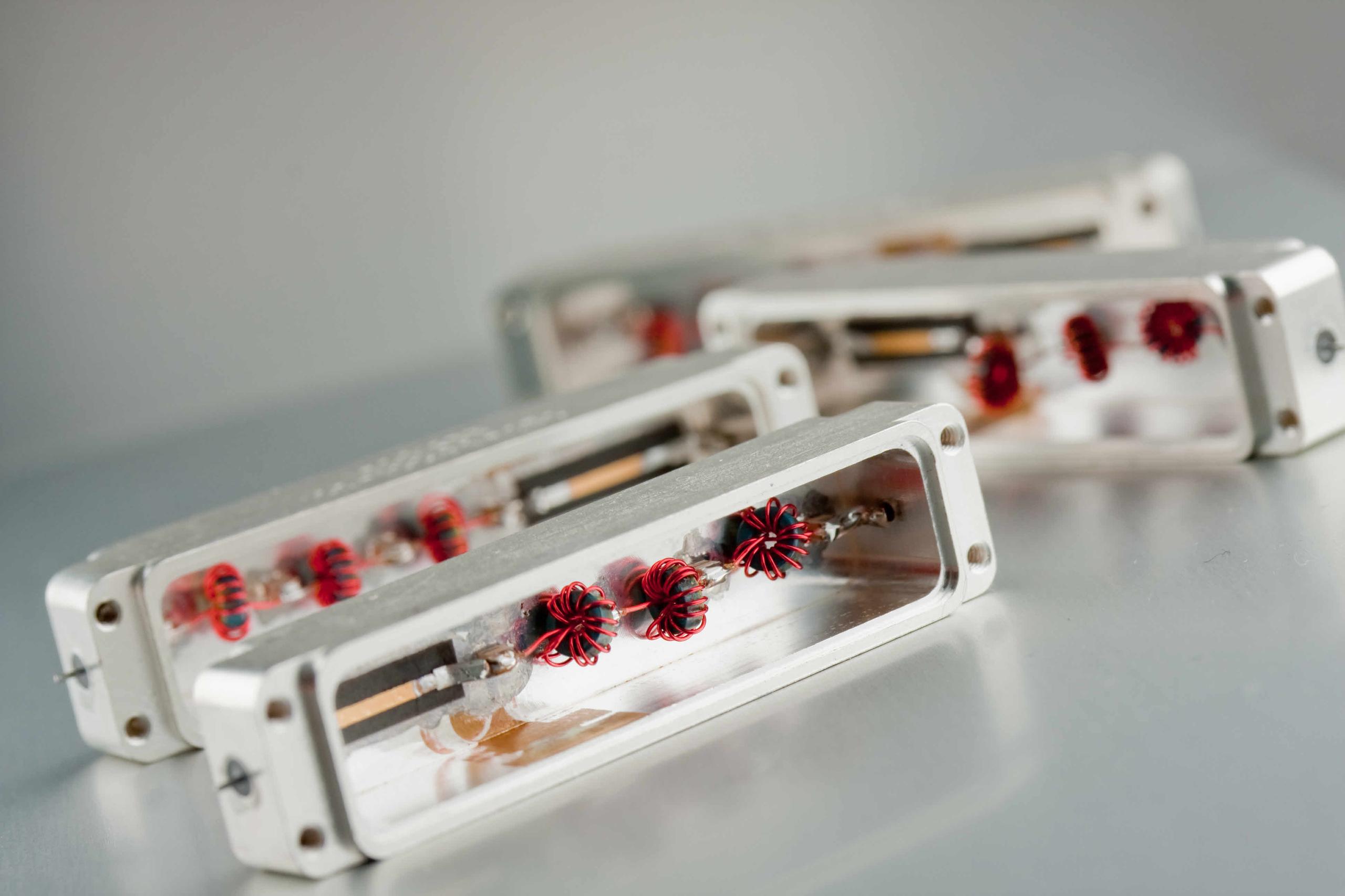
- Strategically placed poles for maximum rejection
- Multiple topologies integrated within a single package for broad frequency coverage
| Frequency | 10 MHz to 3000 MHz | |
| Size | Small | |
| Cost | Low | |
| Harmonics | No Spurious Passbands | |
| Power Handling | Up to 100 Watts |
Built from discrete inductors and capacitors, these lowpass filters cover frequencies from HF through portions of S-band (approximately 10 MHz to 3 GHz). Because discrete components are much smaller than the operating wavelength, lumped element designs achieve a more compact footprint than cavity filters. As distributed-element structures, cavity filters must scale with wavelength and can exhibit spurious passbands or re-entrant responses.
Spectrum Control's lumped element lowpass filters avoid these re-entrant modes, delivering cleaner roll-off characteristics and fractional bandwidths ranging from approximately 10% to 90%, performance that is difficult to achieve with narrowband cavity topologies. Easily tuned using air-spaced inductive coils and built from standard off-the-shelf components, they provide a lower-cost, highly customizable alternative to cavity filter designs.
Spectrum Control’s lumped element filters are designed using discrete inductors and capacitors, covering HF, VHF, UHF, L-band, and portions of S-band (approximately 10 MHz to 3000 MHz). Below 1000 MHz, wavelengths are relatively long; distributed-element filters like cavity filters must be at least a fraction of the operating wavelength, which can make cavities physically larger than other topologies such as lumped elements.
Because discrete capacitors and inductors are much smaller than the operating wavelength, lumped element filters can achieve a smaller footprint than cavity designs.
Distributed-element filters, such as cavity filters, can exhibit spurious passbands, harmonic passbands, or a re-entrant response because their performance depends on the physical dimensions of the structure relative to the wavelength.
By contrast, Spectrum Control’s lumped element filters are smaller than the operating wavelength and therefore do not exhibit re-entrant modes or undesirable harmonic passbands, resulting in a cleaner response. They can also achieve very wide fractional bandwidths (roughly 10% to 90%), which can be difficult to replicate with narrow-band cavity-style topologies.
Lumped element filters are relatively easy to tune by adjusting poles using air-spaced inductive coils. Because these designs typically use standard, off-the-shelf discrete elements and don’t require complex specialized machining (unlike cavity filters), they generally offer lower cost and high customizability.
Cavity Lowpass Filters
Spectrum Control's cavity lowpass filter designs deliver industry-leading insertion loss as low as 0.1 dB, combined with high power-handling capability of up to 400 watts. Through careful process control and component selection, our engineers have developed specialized techniques, including intermodulation suppression, to meet the most demanding customer requirements:
| Lightweight aluminum alloy construction reduces overall unit weight | ||
| NADCAP-controlled gold and silver plating processes | ||
| Proprietary temperature-drift control, holding stability to under 1 ppm/°C | ||
| Cross-coupled pseudo-elliptic topology improves close-in rejection with no insertion loss penalty | ||
| Custom resonator geometry boosts peak power-handling capacity | ||
| Silver-plated resonators and cavity interiors achieve higher Q than standard plating options | ||
| Shock- and vibration-resistant stabilizing structures using low-dielectric-constant materials |
|
Frequency
|
10 MHz to 3000 MHz
|
|
|
Size
|
Small
|
|
|
Cost
|
Low
|
|
|
Harmonics
|
No Spurious Passbands
|
|
|
Power Handling
|
Up to 100 Watts
|
|
These pseudo-elliptic lowpass filter designs reduce the pole count required to meet rejection targets, resulting in smaller, lower-cost filters. The same techniques can also be applied to passband group delay equalization or extended stopband rejection. |
 |
 |
Spectrum Control's low-loss (as low as 0.1 dB) cavity lowpass filters are recognized worldwide for their innovative topologies when performance cannot be compromised. They combine high-Q designs with creative engineering techniques to reduce size while maximizing power-handling capability. |
|
Trusted worldwide in demanding RF applications, Spectrum Control's cavity lowpass filters achieve ultra-low insertion loss of as little as 0.1 dB. High-Q resonator technology, combined with space-efficient designs, delivers excellent power handling in a compact footprint, making these filters an ideal choice wherever performance cannot be compromised. |
 |
 |
Spectrum Control bandpass cavity filters offer ultra-low insertion loss (0.1 dB) because they have very low internal resistance, due in part to plating that is often silver. This means Spectrum Control cavity filter designs are more efficient and better able to handle radiated signal power. Spectrum Control cavity filters can handle thousands of watts; their larger physical surface area compared with lumped element filters, along with the use of air dielectrics, helps prevent arcing that could destroy a traditional lumped element filter. |
|
|
Spectrum Control cavity filters, with their high unloaded-Q designs, can achieve incredibly narrow fractional bandwidths with very steep skirts. This allows Spectrum Control cavity filters to pass a narrow band while heavily attenuating tones just a few MHz away from the band edge. Spectrum Control bandpass filters in a cavity topology are often designed from Invar, which offers a very low coefficient of thermal expansion. This helps ensure Spectrum’s frequency response doesn’t drift as ambient temperatures change, unlike some other manufacturers’ designs. |
|
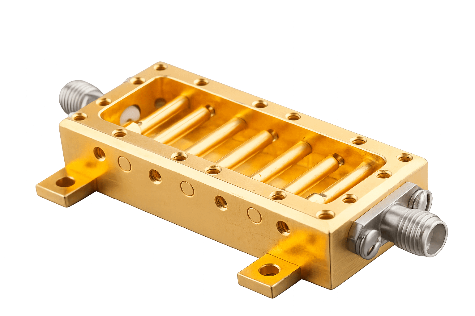
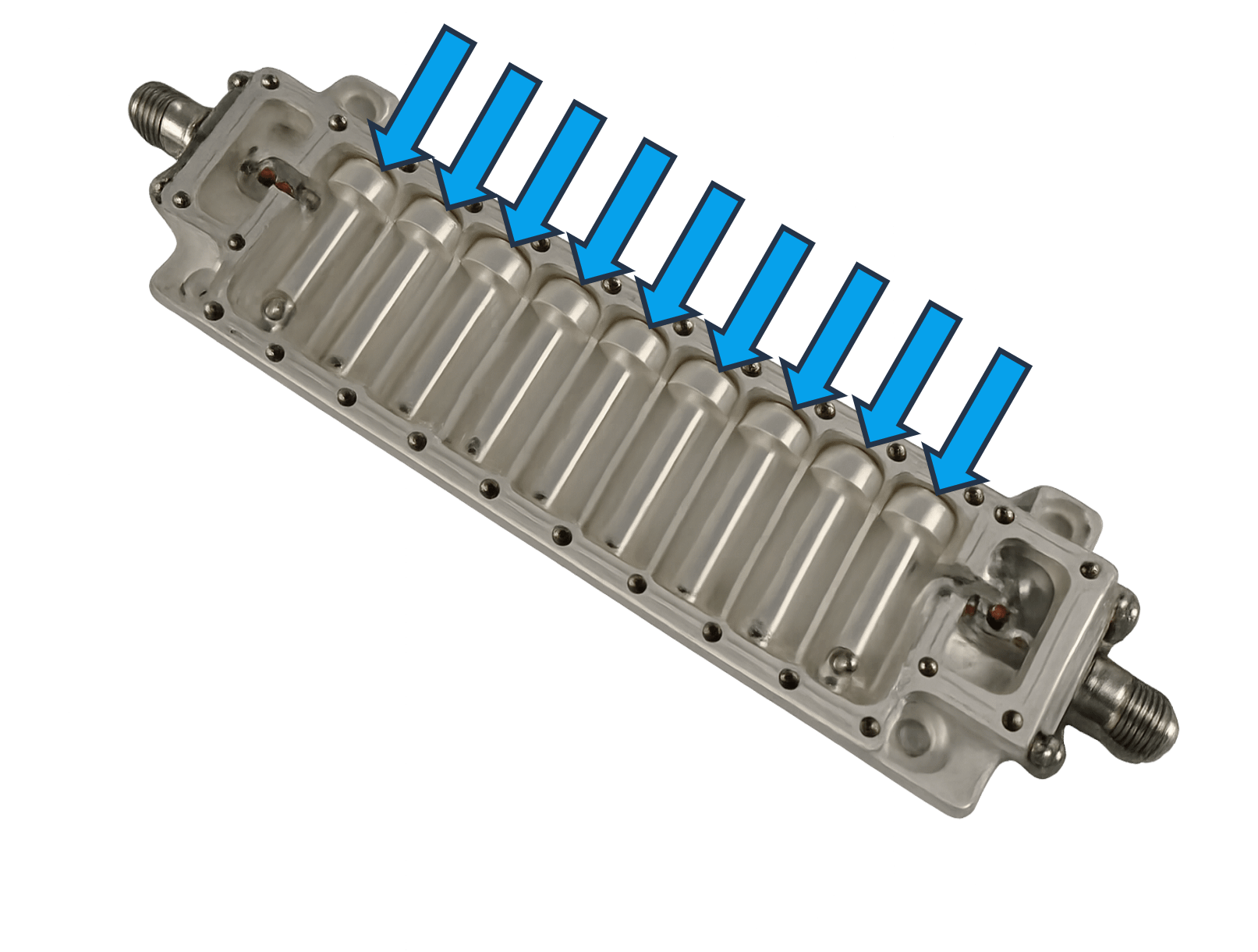
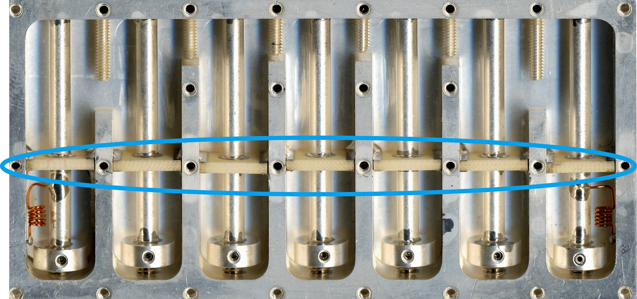
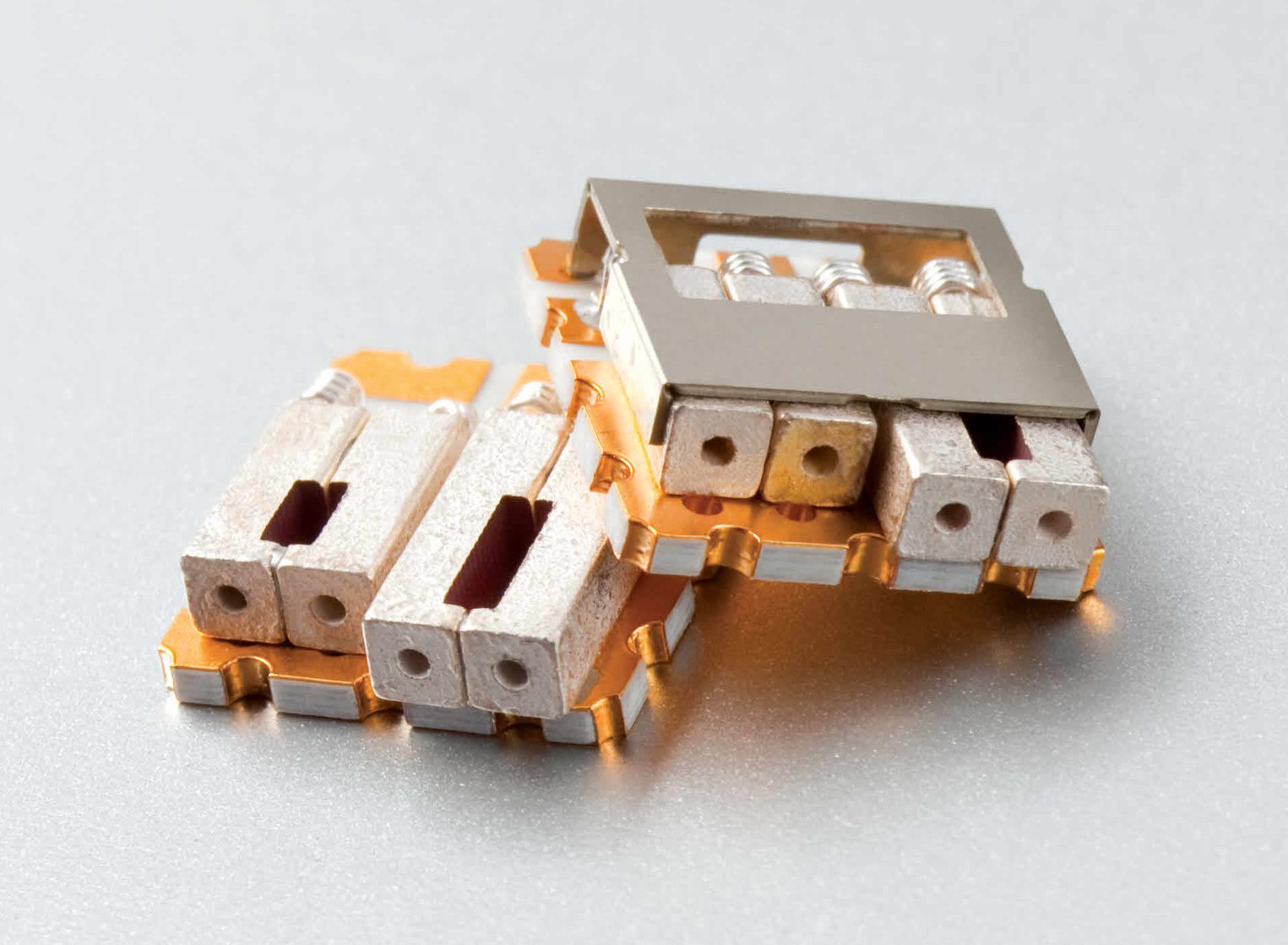
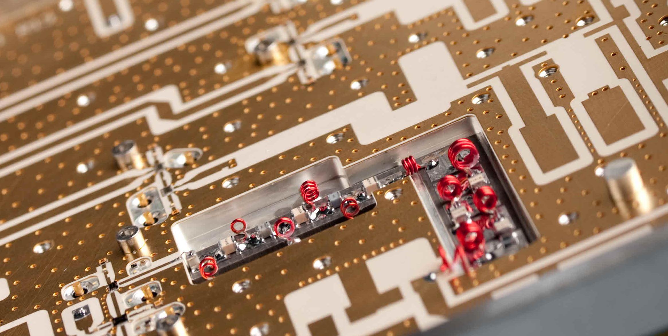
With a Spectrum Control bandpass filter in a cavity topology, the solid metal housing acts like a Faraday cage, preventing EMI from leaking out and external noise from another channel from leaking in. Known for unparalleled attenuation levels, Spectrum Control cavity filters can provide massive attenuation (100+ dB), which is normally difficult to achieve due to parasitic coupling. Unlike some other filter manufacturers, Spectrum Control offers unique resonator designs, like the one pictured here, to reduce overall size and increase peak power handling. |
 |
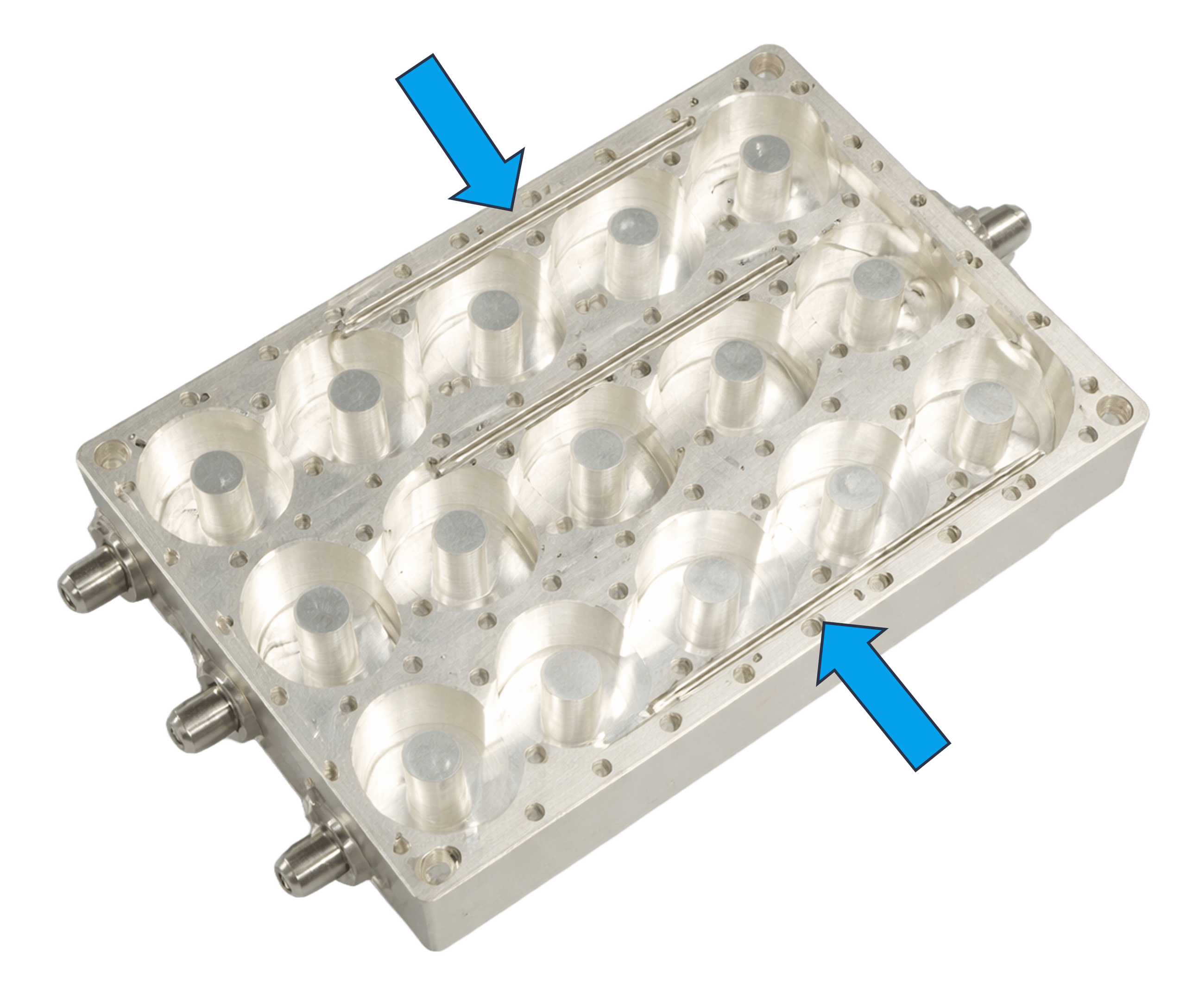 |
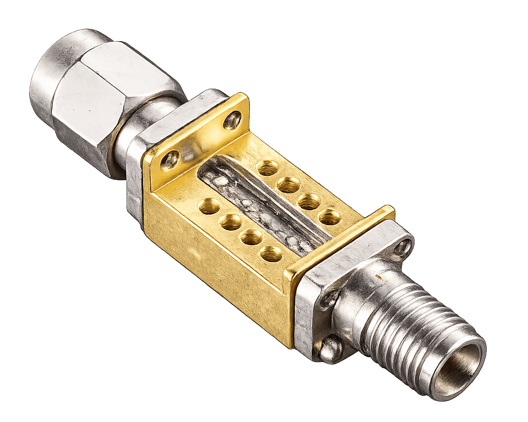
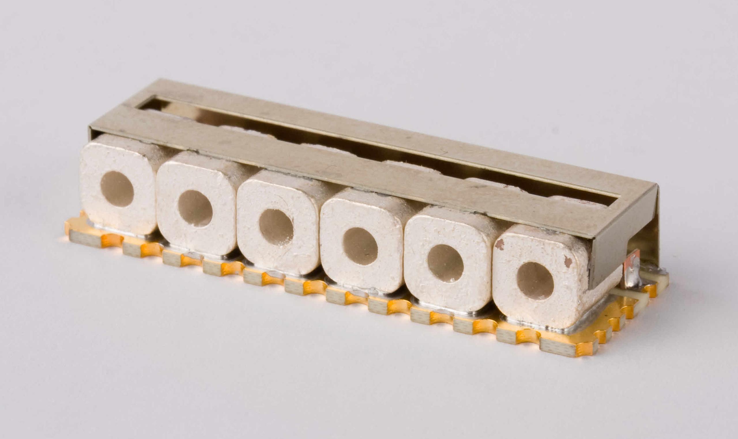
Spectrum Control bandpass filters use unique design approaches to reduce unit size, one of which is iris coupling. Iris coupling transfers electromagnetic energy between adjacent cavities through precisely shaped apertures in the cavity walls. These apertures behave as reactive shunt inductances or capacitances, increasing coupling between resonators and shaping the overall filter response. |
|
Spectrum’s pseudo-elliptic designs incorporate cross-coupling to create transmission zeros, resulting in enhanced rejection performance. Unlike Chebyshev or Butterworth designs, where rejection increases gradually as you move farther from the center frequency, Spectrum Control pseudo-elliptic filters use cross-coupling to force the signal to zero at specific nearby frequencies, creating a steeper skirt between the passband and the stopband. |
 |
 |
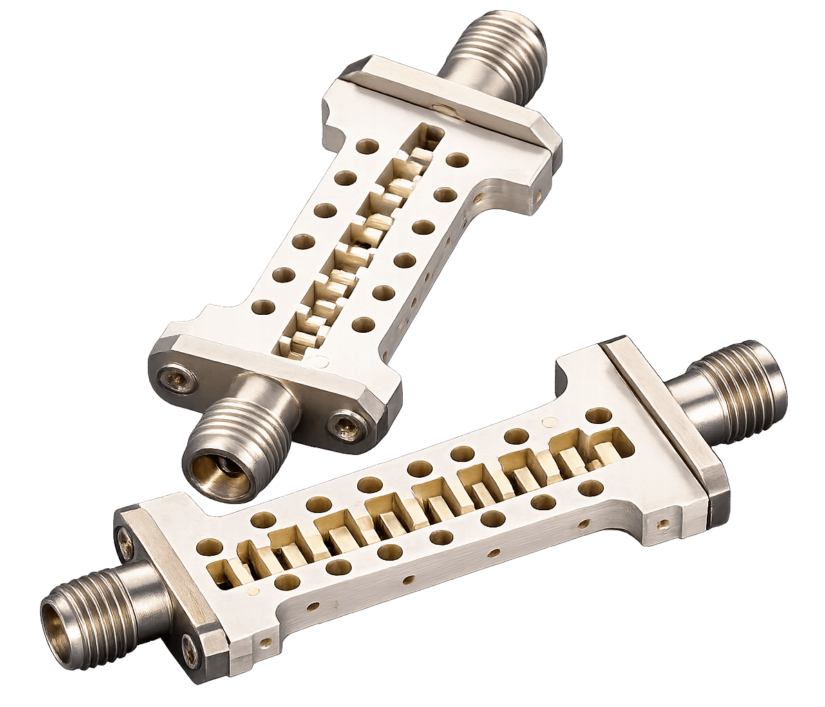
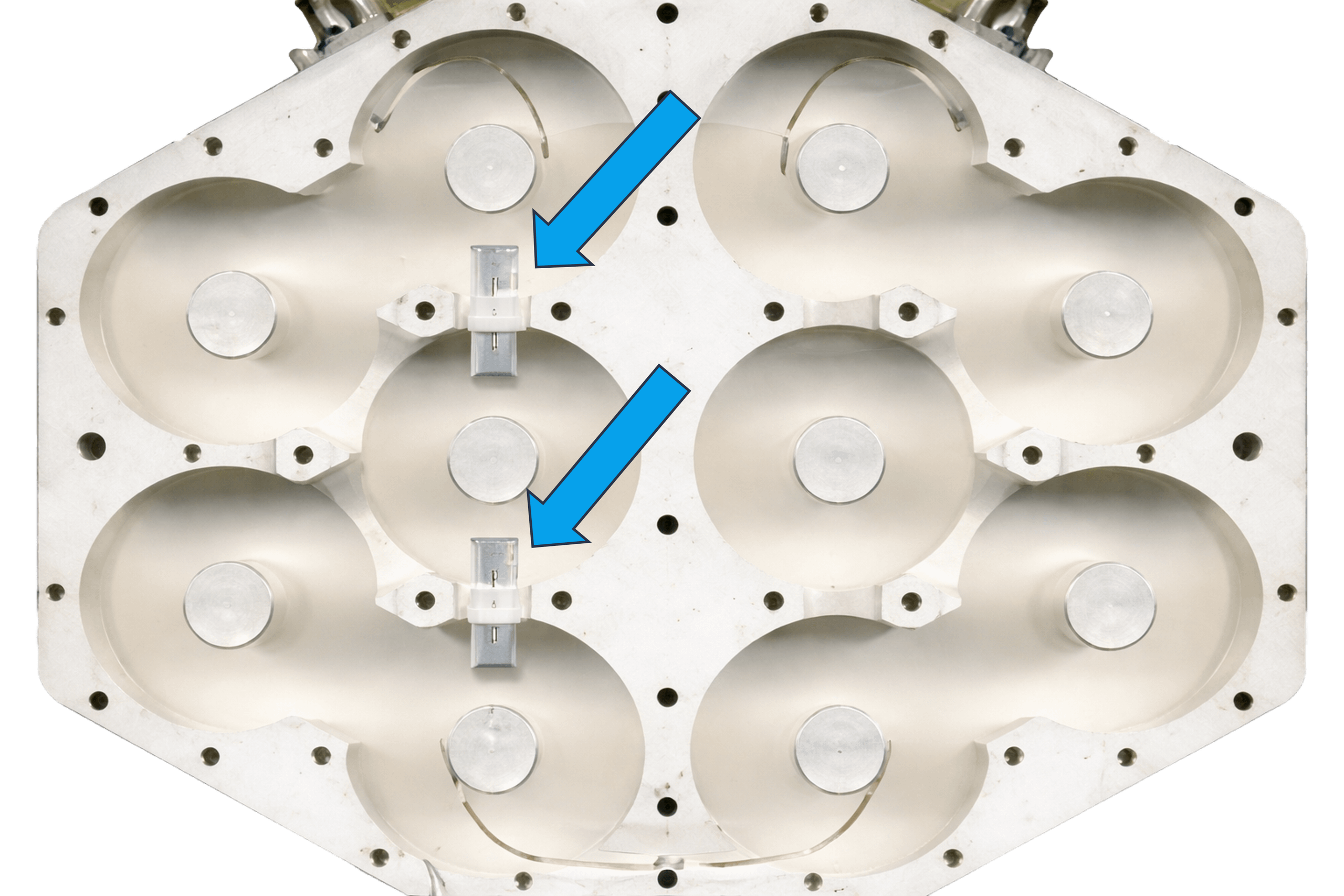
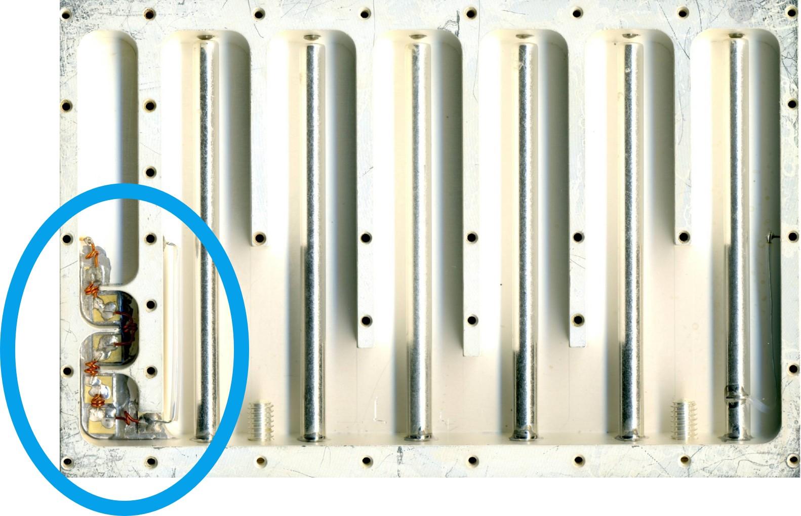
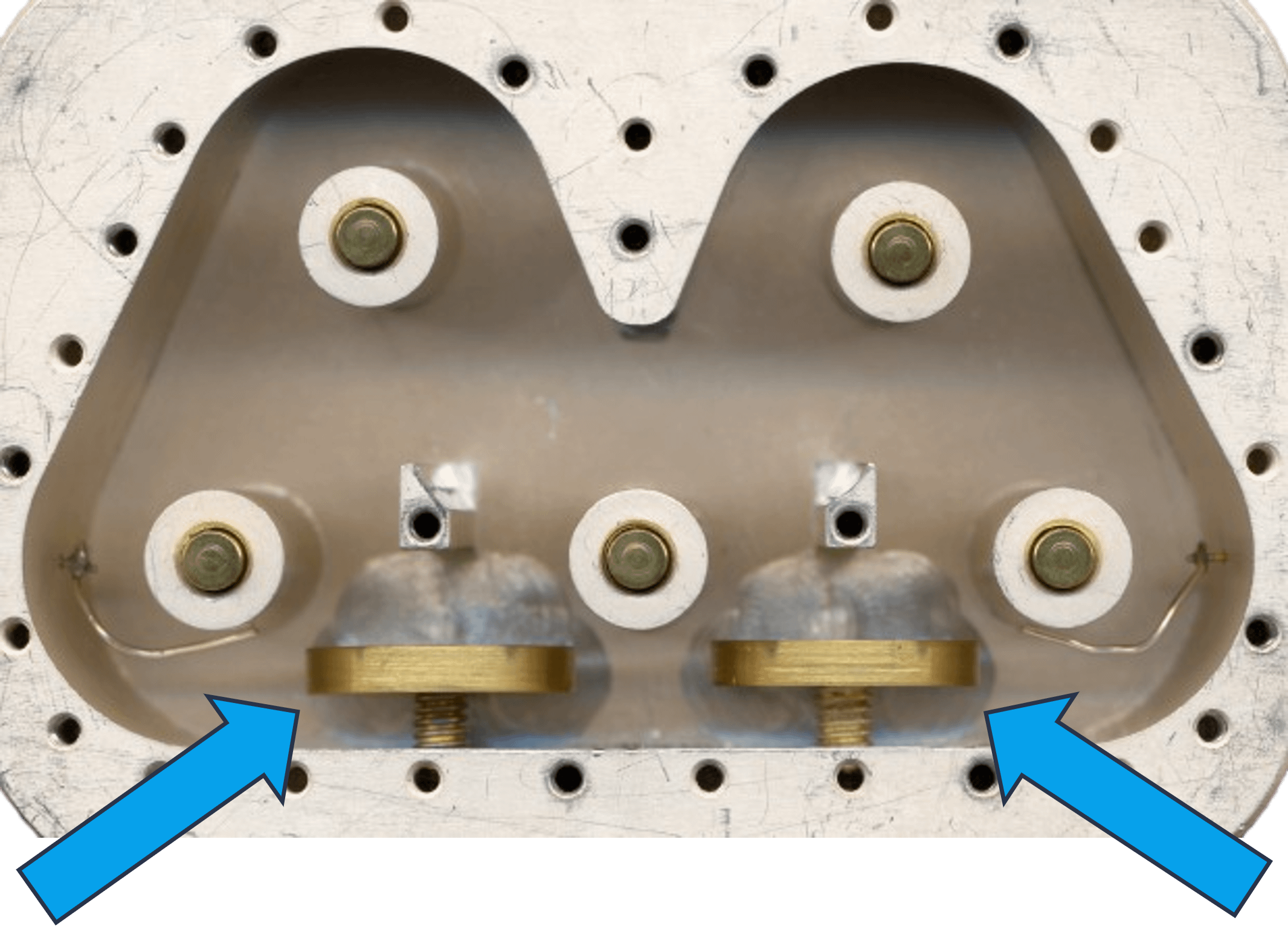
Spectrum Control bandpass filters can incorporate a unique low-dielectric-constant stabilizing structure to reduce overall sensitivity to shock and vibration. Even microscopic shifts in resonator positions can induce microphonics or frequency modulation. If a support structure like the one shown to the left had a higher dielectric constant, even a small movement caused by heating could produce a significant shift in center frequency. These innovative structures from Spectrum Control mitigate shifting effects through three primary mechanisms: they reduce electromagnetic disruptions, add mechanical damping and stiffness, and use low-dielectric materials to reduce mass and weight, making them less likely to shift. |
|
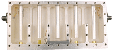
Spectrum engineers routinely use an integrated cleanup low-pass filter to provide extended stopband performance. An integrated cleanup low-pass filter is a complementary filtering stage whose primary role is to suppress multiple harmonic resonances and spurious tones in resonant cavity structures. Without a cleanup low-pass stage, a transmitter could leak high-power harmonics that may interfere with out-of-band receivers. |
 |
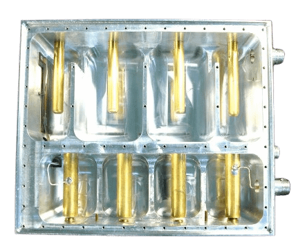 |
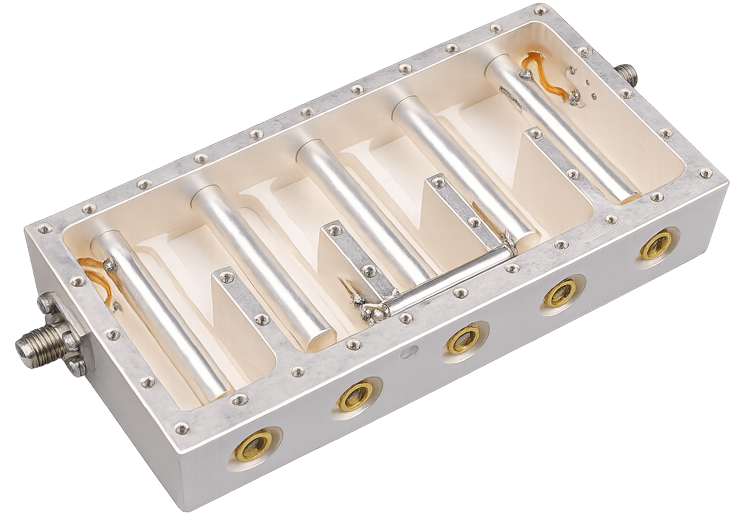
Tightly controlled conductor spacing and surface finish yield very high power-handling capability. Spectrum Control bandpass filters utilize tightly controlled conductor spacing. Cavity filters are naturally high-Q filters; by design, they store significant electromagnetic energy within their resonators or sections. The space, or distance, between the resonator and the interior cavity walls is critical to optimizing power-handling capability. |
|
Using silver plating on our resonators and cavity interiors reduces loss and provides higher Q values than the less expensive plating methods used by other filter manufacturers. Due to its atomic structure, silver has the highest electrical conductivity of any metal. In high-Q Spectrum Control cavity filters, Q is partly defined by the ratio of stored energy to dissipated energy. Using a more conductive finish such as silver directly reduces the amount of energy lost as heat, resulting in higher Q and lower insertion loss. |
 |
 |
Spectrum Control bandpass filters use innovative cross-coupling techniques to achieve optimal rejection by introducing electromagnetic energy between non-adjacent resonators, creating signal paths that cancel at specific frequencies. Spectrum Control also incorporates bimetallic resonators to improve temperature stability, minimizing frequency drift caused by thermal changes that can alter cavity dimensions and shift the center frequency across the band. |
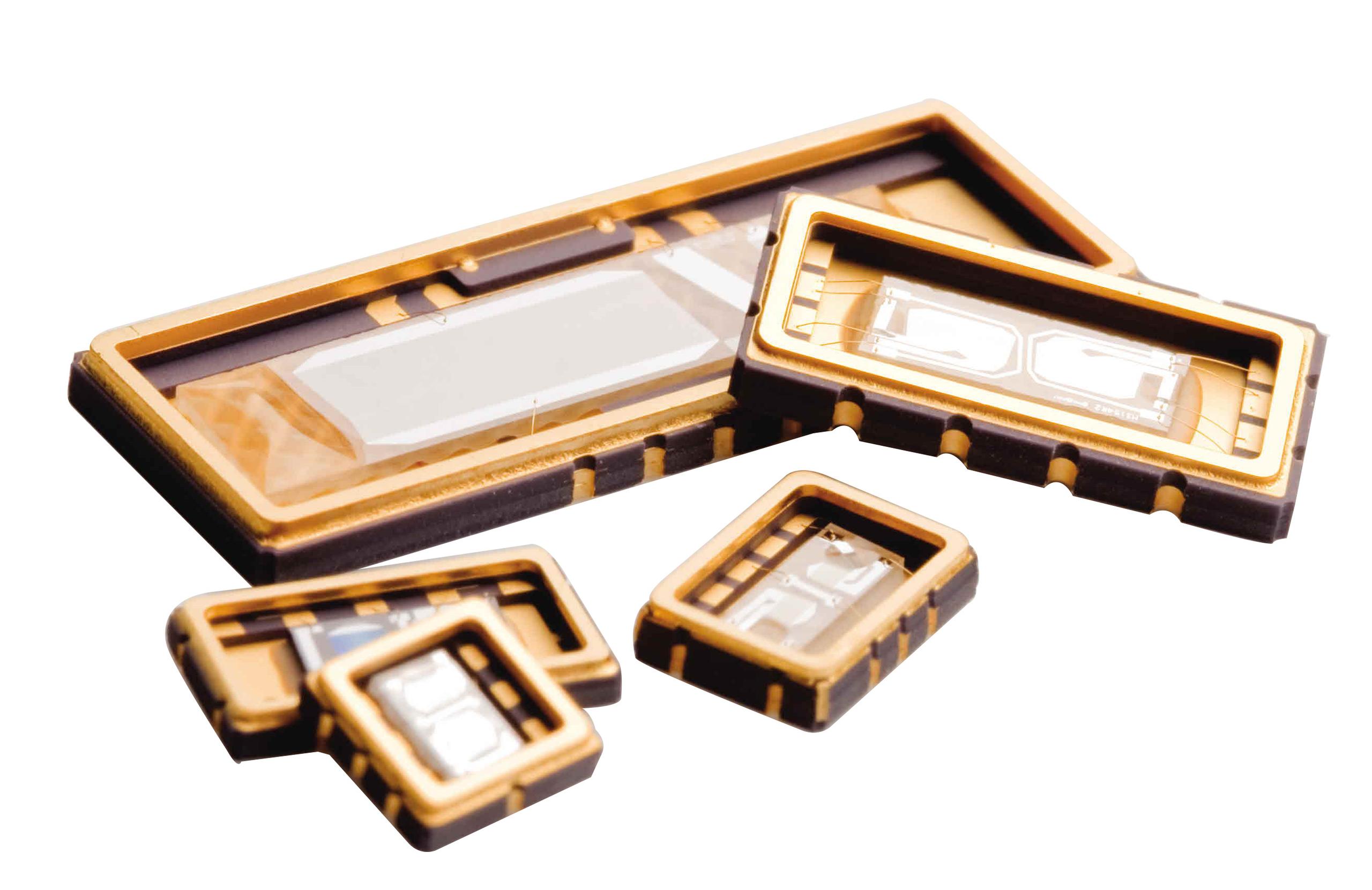
Advanced SAW Filters
Spectrum Control continues to deliver advanced SAW technology for today’s military and commercial markets. These SAW filters, operating at frequencies up to 1600 MHz, offer a range of outstanding features, including:
- Low insertion loss below 2 dB
- Shape factors below 1.1:1
- Fractional bandwidths up to 60%
- 100% tested
- Pre-aged at 100°C
- Gold wire bonds used on all ball bonds to reduce loss
- Silicon thermoset resin to dampen stray acoustic energy and reduce distortion
- Superior group delay performance, as low as 8 ns unit-to-unit
For a view of our SAW Filter models, click here.
Radar Applications for SAW Products
Another branch of SAW technology, particularly for radar applications, uses filters that deliver a linear change in delay across a defined passband. When paired with digital signal processing, SAW-based systems can track targets very effectively, using dispersive SAW delay lines and filters in both the transmitter and receiver to perform pulse compression and expansion. Spectrum Control SAW filters feature extremely steep skirts to isolate signals of interest in crowded or contested spectrum, and defense-grade designs are engineered to withstand shock, vibration, and temperature fluctuations. Low-loss SAW filters also provide ultra-flat group delay, which helps preserve the precise timing required for advanced missile guidance platforms.
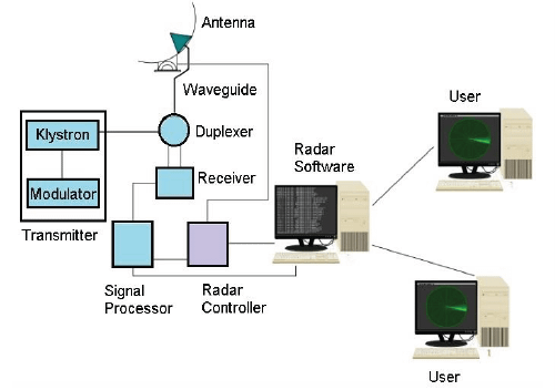
Block diagram for a typical radar system for target detection.
Pulse-compression radar uses dispersive (chirp) filters in both the transmit and receive sections to expand the transmitted waveform and compress the received return, enabling shorter-duration, lower-peak-power transmissions while maintaining sensitivity through improved signal-to-noise ratio. In modern radar applications such as AESA (active electronically scanned array), the antenna electronically steers radio waves without moving the antenna, with each element connected to a compact computer-controlled module that performs both transmit and receive functions.
AESA radars can transmit multiple RF beams at multiple frequencies simultaneously and spread emissions across a wider spectrum, making them harder to detect over background noise while still enabling high-performance operation for ships and aircraft. SAW filters also provide bandpass filtering across many defense applications, including IF filtering in superheterodyne receivers, IF filtering within software-defined radios (SDRs), and IFF, where low-loss designs can deliver high selectivity and low distortion in a smaller, lower-cost form factor than alternative technologies. In superheterodyne receivers, SAW filters are often used as the RF and IF bandpass filters to suppress transmission leakage and interference at RF, and to provide highly selective channel filtering at IF.
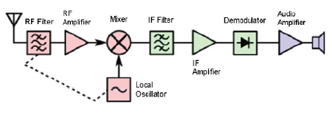
Block diagram of a superheterodyne receiver.
Spectrum Control low-loss SAW filters are also used in transceiver systems and are commonly employed in duplexers within transmit/receive designs.
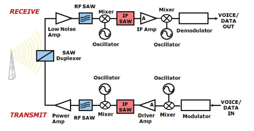
Block diagram of a generic transceiver circuit.
Ceramic Lowpass Filters
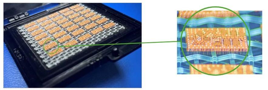
Spectrum Control's engineers specialize in a wide range of filter topologies, including innovative mixed-topology designs integrated into a single package. Our high-complexity ceramic lowpass filters, such as a six-pole, 2100 MHz design with a shape factor of less than 3:1 (45/0.5 dB), deliver exceptional performance while providing outstanding value.
- Gold-plated SMT packaging enhances solderability and corrosion resistance
- Superior performance through alternative coupling structure designs
- Enhanced reliability and repeatability via capacitive coupling arrays
- Compact footprint with ceramic resonators as small as 2 mm
- RoHS-compliant, lead-free solder throughout
- In-house laser sealing available on select designs
 |
 |
3D Glass Lowpass Filters
Spectrum Control continues to advance filter technology with its ultra-miniature glass lowpass filters. Operating at frequencies up to 10 GHz, these high-Q designs offer:
- Many designs achieve under 2 dB insertion loss
- Up to 70 dB of rejection performance
- Stable 1 ns group delay across temperature
- Handles input power up to 1 watt
- Fully customizable to demanding requirements
Suspended Substrate Lowpass Filters
Spectrum Control's low-loss suspended substrate lowpass filters integrate multiple filter topologies within a single package to achieve complex transfer functions while meeting demanding performance requirements. Key features include:
- Combined lumped and distributed elements in one design, boosting unloaded Q and minimizing insertion loss
- Gold vias for superior isolation
- Cauer pole placement for low insertion loss performance
- Integrated cleanup stages for improved broadband performance
Technical Questions
What are the best filter solutions for FR3 and 6G applications?
The answer depends on the portion of the spectrum being used. In an increasingly crowded spectrum, high selectivity becomes essential to separate unwanted signals that may bleed into adjacent bands. Filter functions such as elliptic and Chebyshev are often preferred for their sharp skirts and strategically placed poles. However, these benefits come with trade-offs, including increased insertion loss and group delay variation. Fractional bandwidth selection also becomes critical, as tighter channel spacing drives the need for higher rejection and sharper transitions.
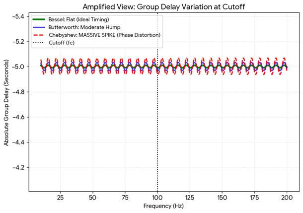
How do I design an RF filter with a constant group delay?
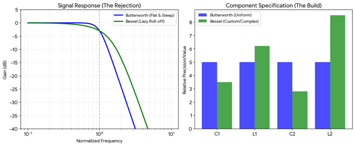
For constant group delay, a Bessel filter is often the preferred choice. It preserves phase linearity, but at the expense of rejection. Its design uses specific non-uniform component values to achieve a flat phase response. At the cutoff transition, the passband has a gentler knee and provides less protection against frequencies on either side of the stopband. If sharp rejection and linear phase are both required, cascading a Bessel filter with additional sections can offer an excellent compromise.
What are the miniaturization limits for high-selectivity filters in SWaP-C applications?
As high selectivity becomes more prominent in the 6G conversation, miniaturization and SWaP considerations will also take priority. Next-generation designs must balance selectivity, insertion loss, and thermal stability with size, weight, power, and cost constraints. Emerging technologies like glass filters offer a compelling option, combining compact size similar to SAW filters with broader frequency capability, operating up to 10 GHz compared to the typical ~1.5 GHz limit of SAW devices, while also providing improved insertion loss performance.
How do I balance Q factor and physical size in a narrowband cavity filter?
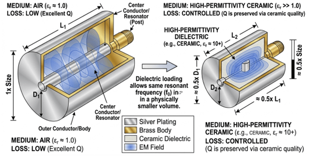
In narrowband cavity designs, unloaded Q and size are inherently linked. Smaller resonators can reduce loss but often increase unloaded Q, while also softening the filter skirts. Because resonators store energy, reducing their size affects selectivity. Introducing ceramic for dielectric loading does not change current flow along the metal resonator but alters the effective wavelength, enabling a more compact design.
What is the relationship between filter order and group delay variation?
All RF filter designs involve trade-offs. As sections and resonators are added, group delay variation increases due to greater energy storage. This is especially critical in emerging 6G applications, where high-speed data requires minimal delay variation. To mitigate these phase effects in higher-order designs, a Bessel function can be employed.
When selecting the optimal shape factor for an RF filter, designers must consider trade-offs between different topologies, guided by the specific platform or application. While shape factor is often a primary concern, factors such as group delay variation, passband ripple, transition sharpness, and insertion loss can significantly impact overall RF chain performance.
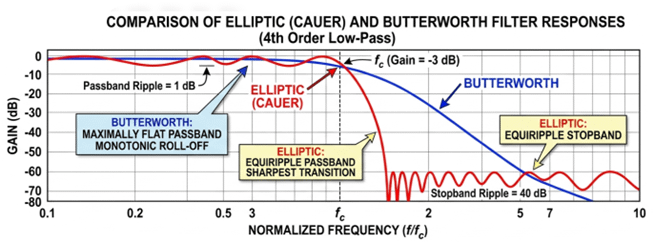
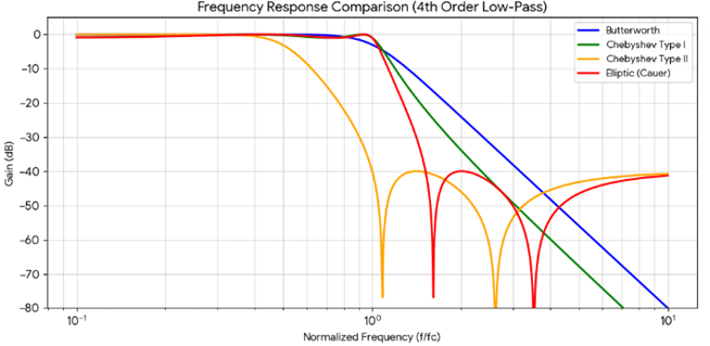
RF filter design firms like Spectrum Control typically select from four main transfer functions based on application needs. Butterworth filters are preferred for their maximally flat passband, achieved through symmetrically distributed poles. However, this ripple-free response results in a more gradual transition into the stopband.
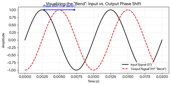
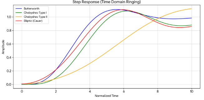
If minimizing group delay variation and phase deviation is the goal, a Bessel function is typically preferred. Its poles are positioned to maintain a nearly constant group delay across the passband. As the signal approaches cutoff, reactive elements store and release energy, increasing phase shift. In a Bessel design, this phase response remains smooth and uniform, much like a well-banked curve, ensuring signals exit with minimal distortion.
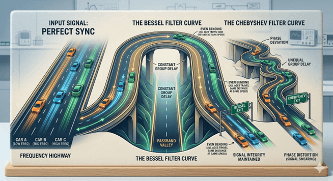
In contrast, a Chebyshev filter prioritizes sharp rejection, resulting in a more abrupt and less uniform phase response. The “curve” is tighter and less synchronized, causing signals to exit at different rates, an effect analogous to phase distortion.
With a Bessel function, phase linearity is preserved, but rejection is reduced. The design uses specific, non-uniform component values to achieve a flat phase response. At cutoff, the passband exhibits a gentler knee, offering less attenuation of frequencies near the stopband.
When maximizing steep skirts, rejection, and sharp roll-off, a Chebyshev function is often preferred. It offers a more pronounced shape factor than Butterworth or Bessel filters, but introduces passband ripple as poles cluster near the cutoff frequency. This results in non-linear phase response, increased group delay variation, and potential signal distortion near the band edges.
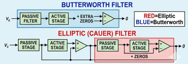
For even sharper rejection, elliptic (Cauer) filters provide a near “brick-wall” response with excellent selectivity. They achieve this through both pole placement near the passband and transmission zeros in the stopband. However, elliptic filters exhibit ripple in both passband and stopband and have highly non-linear phase response, making them less suitable for phase-sensitive applications.
Because steep rejection is prioritized, phase linearity is significantly degraded. Group delay variation increases near the band edges, introducing distortion. As a result, Cauer (elliptic) functions are generally not well suited for time-domain applications such as phased-array radar.
In conclusion, when selecting a filter function, selectivity, insertion loss, and rejection should not be the only considerations. Group delay variation and phase deviation can be equally important, depending on the intended application and platform requirements.