PRODUCTS / COMPONENTS / FILTERS / MULTIPLXER SOLUTIONS
RF Diplexers
A diplexer is a design that receives an RF signal, splits that signal into two distinct paths, and ultimately routes it to two ports. This function is typically accomplished using a combination of high-pass and low-pass filters, as well as channelized structures, to achieve the isolation required for effective signal separation. When two signals reach the common input port, the lower-frequency signal sees a low-loss pathway through the low-pass channel but encounters a high-impedance, high-rejection barrier at the high-pass channel. Likewise, the higher-frequency signal is rejected by the low-pass channel and directed through the high-pass channel.
By effectively isolating the signals and the two channels, a diplexer ensures that nearby transmitters do not leak RF energy into one another, preventing signal distortion. The sharp rejection outside the intended passbands ensures that out-of-band signals are blocked, minimizing system interference. One of the primary challenges in diplexer design is achieving proper impedance matching at the common input point. If the two filter circuits that separate the frequency bands are not precisely matched, signals will encounter an impedance mismatch and be reflected back toward the source, resulting in standing waves, increased reflections, and unwanted insertion loss.
Visit our filter customization tool to optimize your demanding diplexer requirements. Our extensive library of low-loss designs can reduce the need for additional gain, supporting SWaP-constrained applications. Spectrum engineers apply innovative techniques to deliver high-performance solutions.
Role of Diplexers
Diplexers play a pivotal role in RF systems by enabling two signals to coexist within a single signal path while allowing them to be separated at the output ports. Instead of requiring two completely independent signal paths at this point in the RF chain, a diplexer allows an RF engineer to consolidate signal routing, reducing hardware complexity and improving system efficiency.
Because each channel exhibits high rejection outside its designated passband, the diplexer ensures that signals remain isolated even while sharing the same physical package. This isolation is especially important in systems where transmit and receive paths operate simultaneously or where multiple signals operate in closely spaced frequency bands with minimal separation.
Mixed Topologies
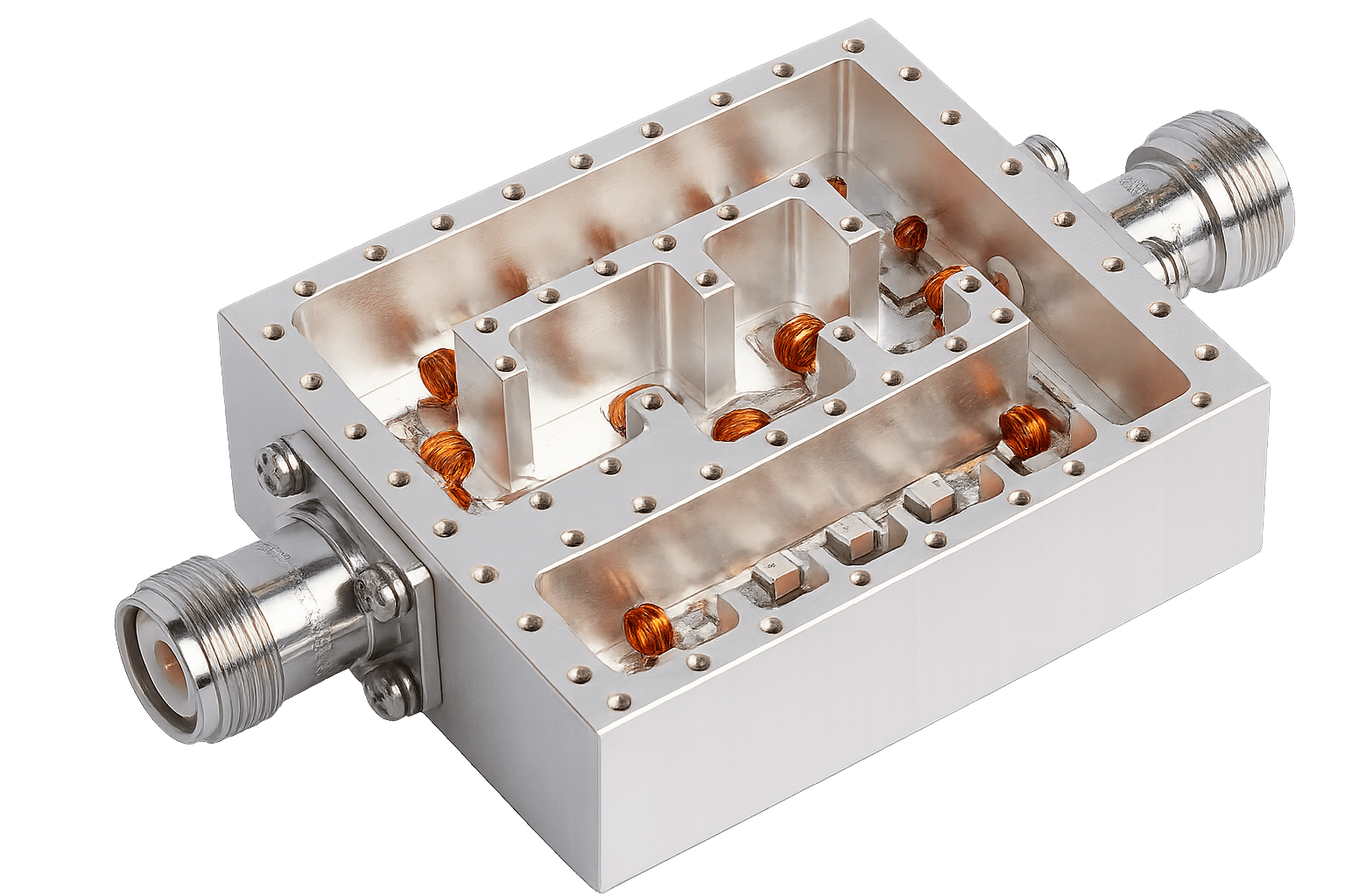
In some systems, a single filter topology, such as a cavity or lumped-element design, may not satisfy the bandwidth, insertion loss, or rejection requirements of each frequency band. In these cases, diplexers can employ multiple filter topologies, with each channel optimized for its specific frequency range or application. For example, a lumped-element design may better serve the lower-frequency channel, while a cavity filter may be used for the higher-frequency channel, where its higher Q-factor and lower loss characteristics provide superior performance.
This mixed-topology approach allows engineers to balance competing—and sometimes conflicting—requirements within a single device. Combining filter technologies can also reduce the overall diplexer footprint, particularly when lumped-element circuits are integrated with cavity-based structures.
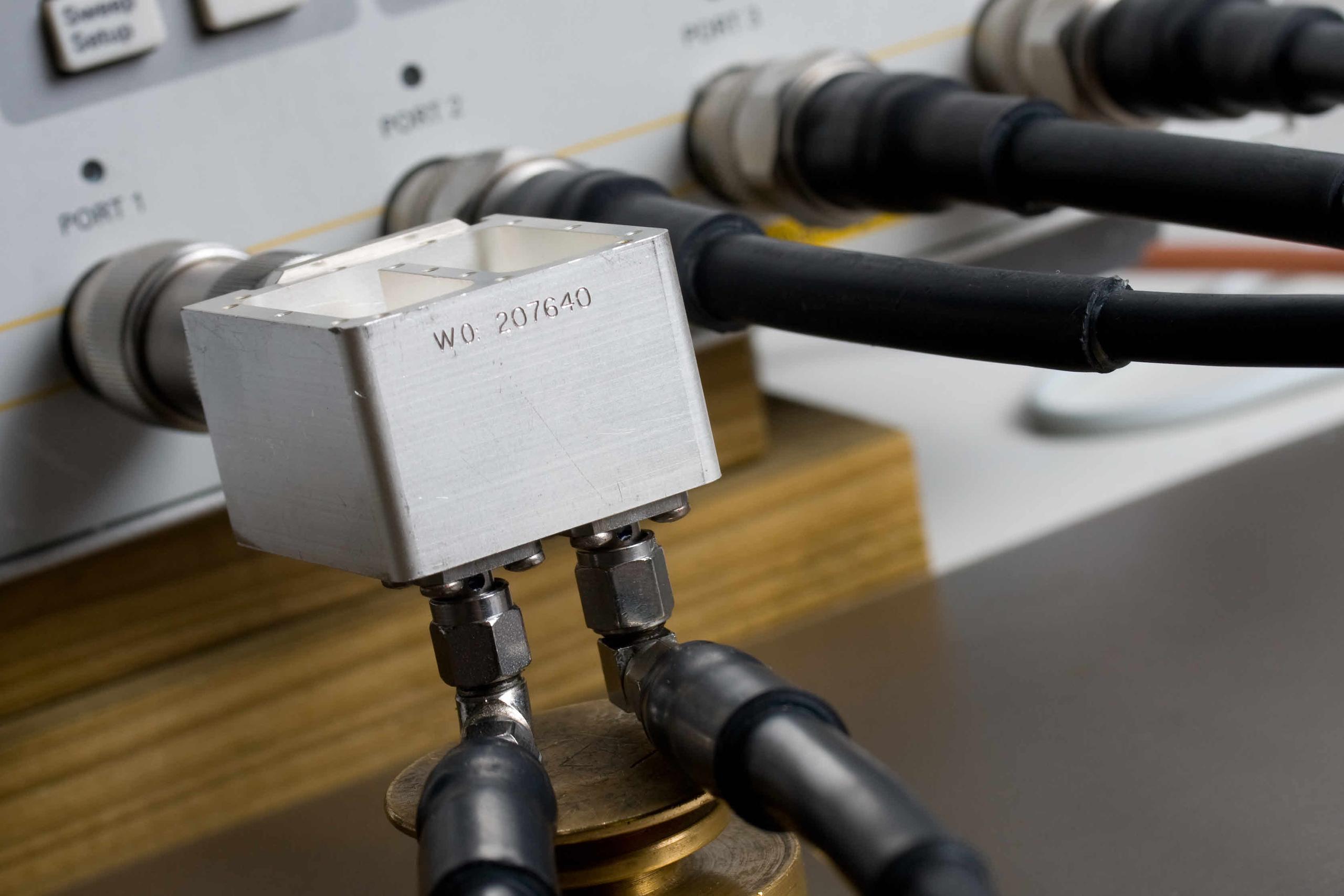
Novel Packaging
Creative layouts are a hallmark that set some diplexer manufacturers apart from others. This design required bottom-mounted terminations to ensure precise alignment with the customer’s existing ports. By adapting the mechanical interface to the platform requirements, Spectrum Control was able to simplify integration while maintaining RF performance and minimizing system redesign.
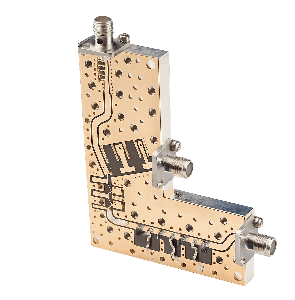 |
Spectrum Control diplexer engineers utilize suspended-substrate topologies for ultra-broadband applications. Suspended-substrate designs are ideal because they bridge the gap between cavity filters, which are larger, and microstrip designs, which typically exhibit higher loss. By suspending the PCB in air between two metal ground planes, suspended-substrate diplexers replace the solid dielectric material with air as the primary dielectric, reducing loss and improving overall performance. |
|
Diplexer objectives are not always limited to passing desired signals; in many applications, they are also required to reject high-power unwanted tones. This challenge was addressed through a pole-placed high-pass/low-pass notch diplexer design that provides high rejection while maintaining low insertion loss in the desired passbands. |
|
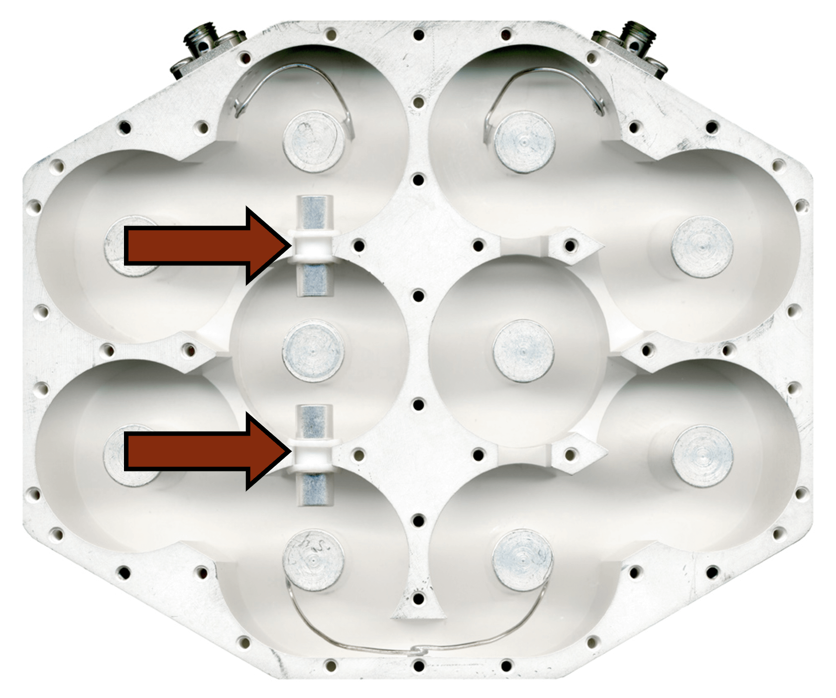 |
Spectrum Control diplexers incorporate cross-coupling techniques to create transmission zeros, resulting in enhanced out-of-band rejection and improved selectivity. |