SAW Filters
Low insertion loss SAW filters (1 dB) are essential for many of today’s defense platforms and modern wireless environments that require high spectral fidelity. Spectrum’s Advanced SAW Filters (1 dB) provide narrow shape factors, a wide variety of fractional bandwidths from 0.04% to 60%, and hermetic packaging for demanding applications. Spectrum Control offers 1 dB loss SAW filters to help identify weak communication transmissions as well as recognize valuable intelligence signals in a crowded spectrum.
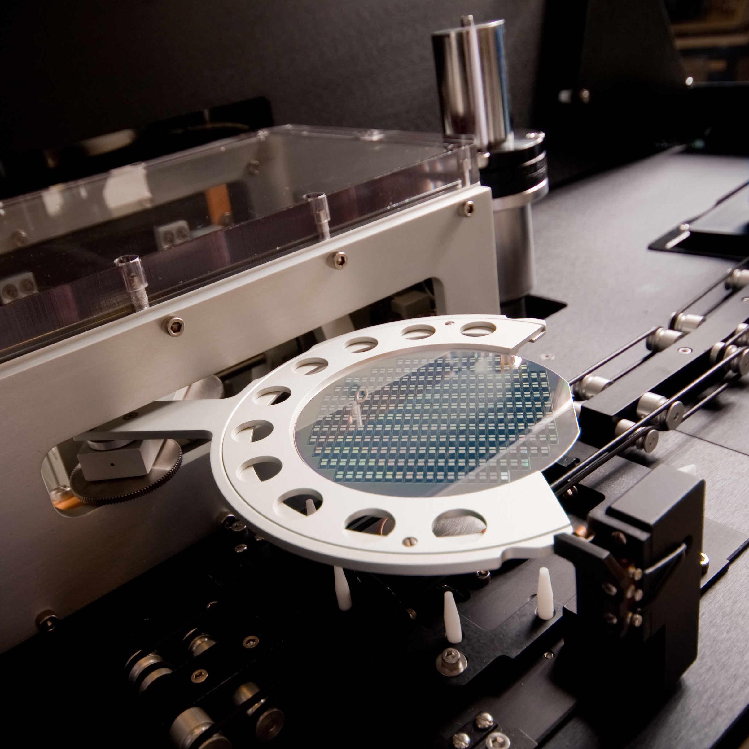
Spectrum’s lithography process enables smaller geometries down to 0.35 microns for superior insertion loss performance. Our database of low-loss SAW filter designs (1 dB) helps eliminate the need for additional gain when Size, Weight, and Power (SWaP) initiatives are in place. Spectrum assures specification compliance with 100% on-wafer probe testing of all SAW designs. Low-loss SAW filters from Spectrum Control also help suppress harmonics on a receiver front end when complex pulse or chirp signals are cascaded in the receive-side chain, critical when flat amplitude response helps prevent distortion and unwanted spurious modulation. Spectrum Control’s line of low-loss SAW
Scroll down to see all available options ↓
filter designs (1 dB) offers insertion loss as low as 1 dB while achieving high rejection in a compact design.
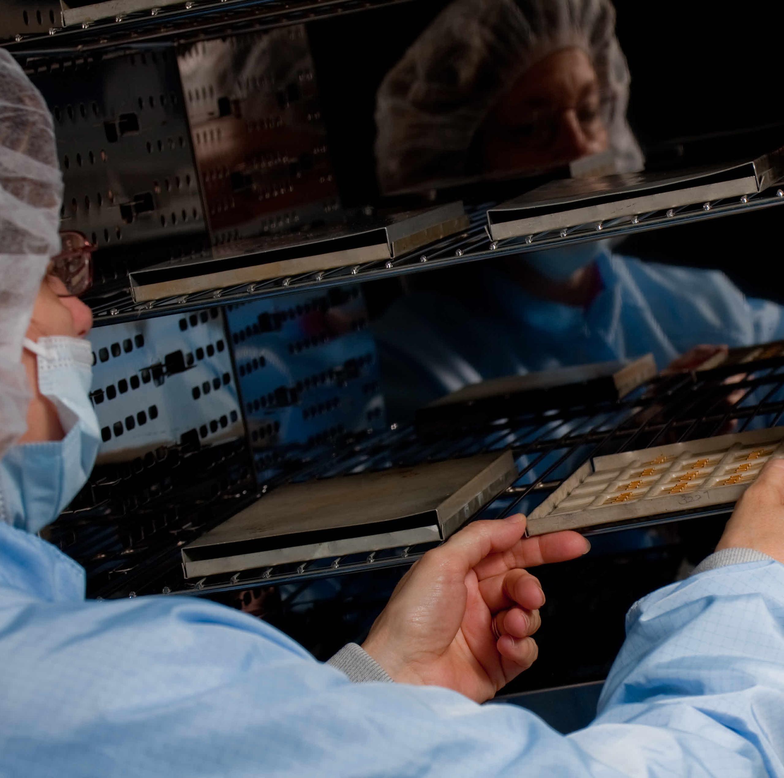
Spectrum Control pre-ages 100% of its SAW filters at 100°C. This critical stabilization step locks in center frequency performance to within 0.0005%.
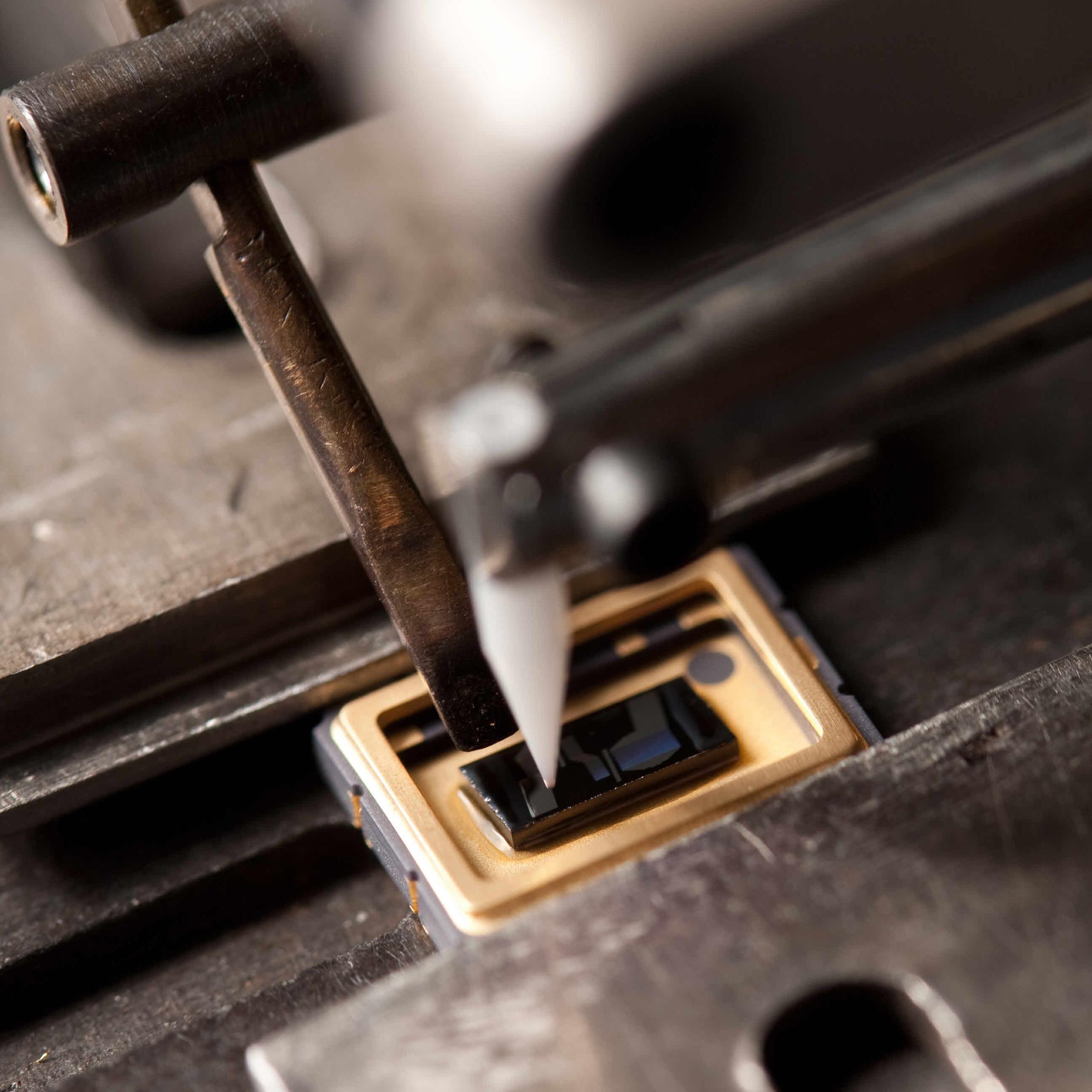
These low-loss SAW filters (1 dB) use gold wire for all ball bonds. Spectrum also incorporates a silicon-based thermoset resin, which further dampens stray acoustic energy and reduces signal distortion in the passband.
Spectrum incorporates 100% backside particle impingement or planar etching during production. This important step minimizes bulk modes while simultaneously improving spurious rejection. This automated process isolates the traveling wave, further enhancing rejection and lowering insertion loss (1 dB).
Visit our SAW filter customization tool to help optimize your demanding filter requirements today.
|
High Frequency Lithography
Modern stepper imaging technology enables smaller geometries and uniform finger widths as small as 0.35 microns, leading to superior insertion loss and higher frequencies up to 1600 MHz.
|
 |
100% Pre-Aging
Spectrum Control ensures that all SAW filters are pre-aged at 100°C. This critical stabilization step locks in center frequency performance to within 0.0005%.
|
 |
|||
|
Precision Bonding
In addition to using gold wire on all ball bonds, Spectrum Control incorporates a silicon-based thermoset resin that dampens stray acoustic energy and reduces signal distortion in the passband.
|
 |
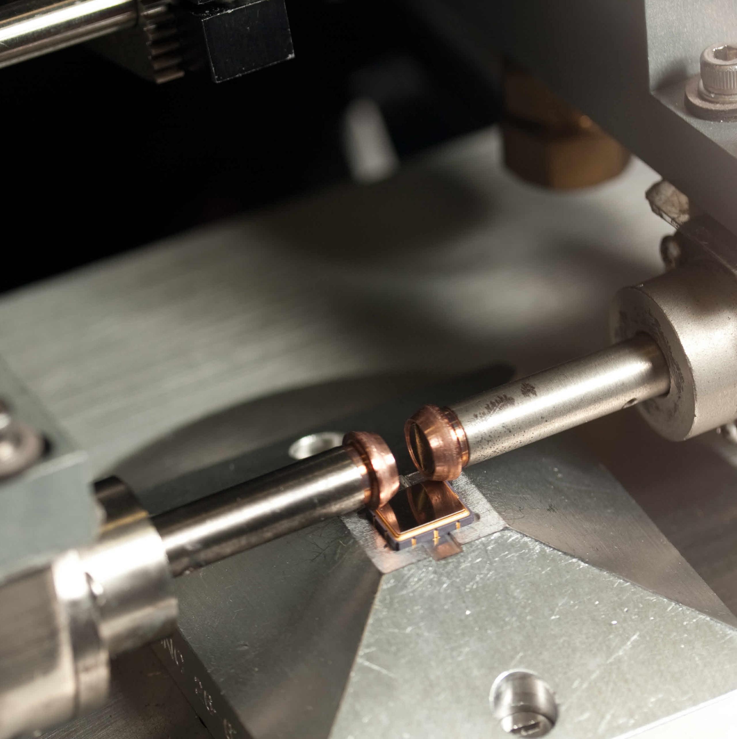
Hermetic Sealing
Spectrum Control uses hermetic seam sealing to ensure a reliable seal and stable environment for sensitive package contents, meeting MIL-STD-883 Method 1014, Conditions A & C.
|
 |
Results:
Didn’t find the product that meets your specifications?
Submit your custom requirements
here.
All Items
Brochure
Datasheet
Design Guide
Success Story
Whitepaper
Brochure
Datasheet
Design Guide
Success Story
Whitepaper
Whitepaper
Solving Modern Spectrum Management Challenges with Custom Microwave Filters
SAW Filter Technology: Compact, High-Performance RF Filtering Solutions
Spectrum Control offers a wide range of low-loss Surface Acoustic Wave (SAW) designs, blending high power handling with low insertion loss into a single customizable solution.
In theory, an ideal SAW filter would exhibit no loss, an instantaneous transition from the passband to the stopband, infinite stopband rejection, no signal distortion introduced by the filter, and minimal size and cost. In reality, many trade-offs must be considered when selecting a suitable SAW filter. One advantage of SAW filter technology is the ability to realize components with reduced size and weight, and therefore lower cost, compared to other filter technologies, since the same types of process equipment used by IC manufacturers can be adapted to manufacture SAW products.
A SAW filter operates by converting electrical energy into acoustic (mechanical) energy on a piezoelectric material. This piezoelectric effect is initiated using two interdigital transducers. The input transducer converts the incident electrical signal into acoustic waves, while the output transducer receives the acoustic waves and converts them back into electrical energy. These waves are generated equally in both the +X and −X directions by the transducer, a configuration known as a bidirectional transversal filter. Because only half of the generated wave (the +X direction) is utilized, a 3 dB loss is observed. When both the input and output transducers are considered together, the resulting processed signal exhibits a total insertion loss of approximately 6 dB.
 |
 |
|
|
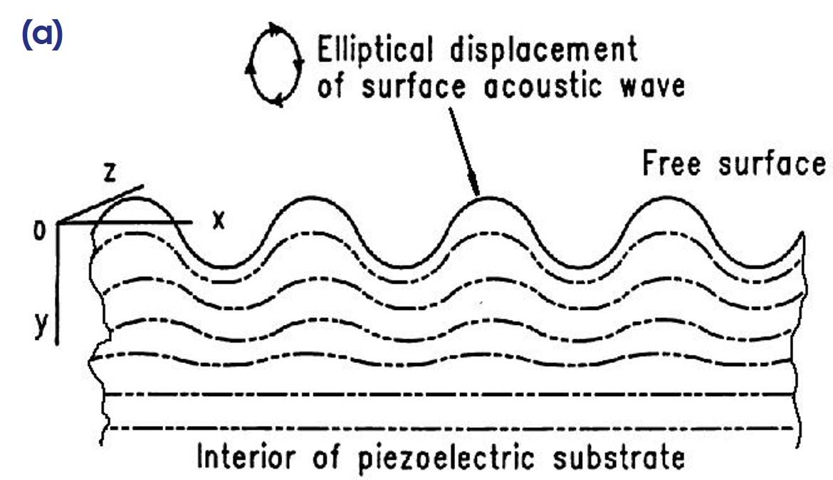
Diagram of a Surface Acoustic Wave travelling on substrate surface. (Courtesy of C.K. Campbell, Ph.D.:
Supplemental notes on lectures on SAW Devices, 1985)
|
Bi-directional operation of a typical transversal device with equal SAW generation in -X and +X directions.
(Courtesy of ‘SAW fundamentals’, SAWTek, 2/15/2001, p. 2).
|
Each transducer is composed of periodic interdigital electrodes connected to two bus bars, which are in turn connected to the electrical source or load. A single interdigital electrode acts as an acoustic source or detector; its amplitude is determined by the electrode length, while its phase is defined by the electrode’s position. The wavelength (λ) formed by the electrodes and the adjacent gaps determines the operating frequency of the SAW device.
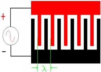
Diagram of a basic transducer and a photograph. Golden colored area represents the patterned metal against the piezoelectric substrate.
With this general arrangement, the acoustic energy, concentrated at the crystal’s surface, is easily accessible for signal processing.
|
Substrate
|
Velocity (m/s)
|
Tc (ppm/°C)
|
Coupling Coefficient (K2)
|
Applications
|
|
YZ Lithium Niobate
|
3488
|
94
|
0.045
|
Wide band filters, long delay time delay lines
|
|
128° Lithium Niobate
|
3992
|
74
|
0.055
|
Wide band filters
|
|
Quartz
|
3158
|
-0.033ppm/°C
|
0.00116
|
Narrow band filters, short delay lines, resonators
|
|
112° Lithium Tantalate
|
3290
|
18
|
0.0075
|
Mid band filters
|
|
41° Lithium Niobate
|
4792
|
50
|
0.172
|
Low loss filters
|
|
64° Lithium Niobate
|
4792
|
70
|
0.113
|
Low loss filters
|
|
42° Lithium Tantalate
|
4022
|
40
|
0.076
|
Low loss filters
|
Table shows the most common materials used for the manufacture of SAW product.
Each material possesses qualities that work best for a certain segment of each SAW filter type.
The Tc value, or temperature coefficient, represents the shift in center frequency as a function of the operating temperature of the SAW component. With the exception of quartz substrates, the filter center frequency shifts upward at lower temperatures and downward at higher temperatures in a linear manner. These frequency shifts are accounted for during the SAW design process by adding a temperature-shift margin to the passband requirements and subtracting it from the stopband requirements.
For quartz substrates, the temperature shift is downward and parabolic, with a turnover temperature at which the temperature coefficient is zero. This turnover temperature can be adjusted by selecting quartz with different cut angles to achieve optimal performance over the customer’s specified temperature range.
The coupling coefficient (K²) represents the efficiency with which a material generates acoustic waves. Materials with larger K² values produce stronger acoustic waves and generally exhibit lower loss per unit delay (substrate length), allowing for wider filters or longer delay lines.