PRODUCTS / COMPONENTS / FILTERS /
Filtered GPS LNAs
Spectrum Control offers a complete line of filtered GPS low-noise amplifiers ideal for applications where high reliability is critical. These filtered GPS low-noise amplifiers are designed to reduce out-of-band interference while achieving high dynamic range.
The integrated LNAs provide 45 dB of gain with a low 1.8 dB noise figure.
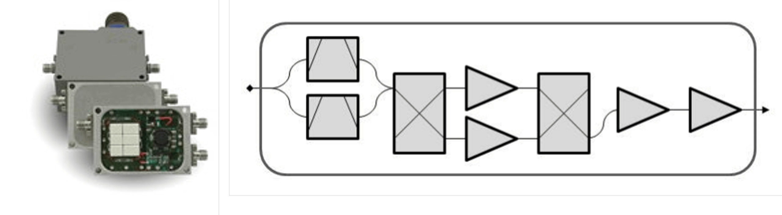
A single ceramic filter or a pair of diplexed ceramic filters with 3-pole responses select only the desired GPS signals, while the low-noise gain stage maintains the receiving system’s sensitivity.
Spectrum Control’s pre-filtered GPS LNAs amplify only the desired GPS signals while protecting the receiver front end from interference in increasingly crowded electromagnetic environments. By combining low-loss filtering, amplifier expertise, and precision mechanical design, these modules maximize out-of-band rejection, preserve low noise figure, and maintain a compact footprint.
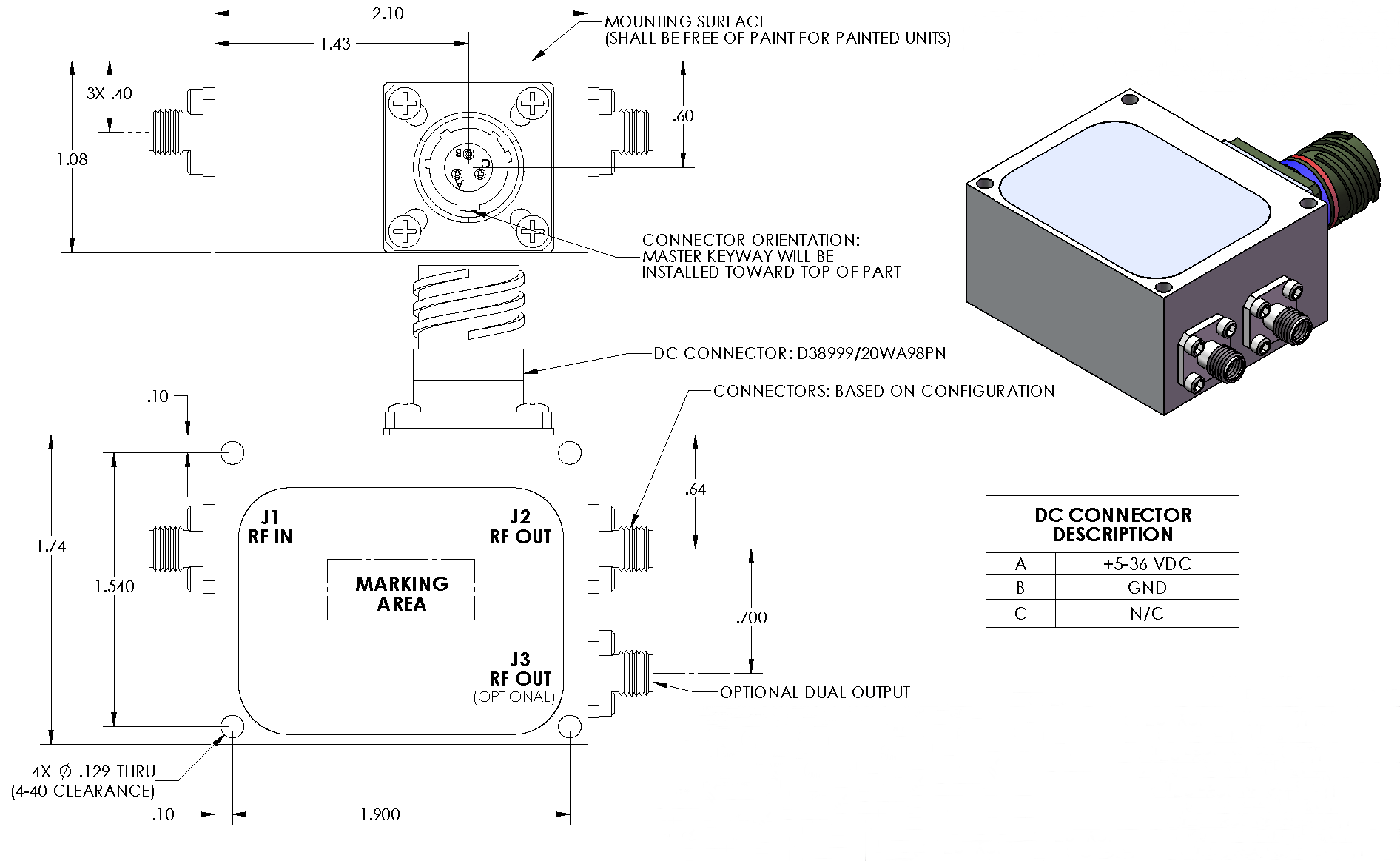
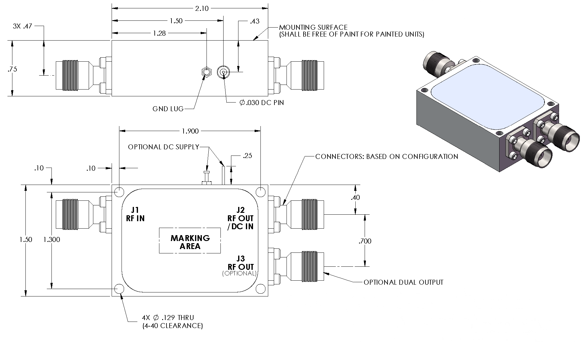
Available in multiple band configurations, gain levels, supply voltages, output options, and connector styles, Spectrum Control's LNAs deliver strong anti-jam performance and industry-leading dynamic range. DC power can be applied directly through the output connector or via an optional external bias port.
These high-performance Filtered GPS LNAs offer rich features including:
- Nickel plated package
- SMA, N, or TNC connectors
- Coaxial or external bias connection
- Bias options including +5 VDC, 5-16 VDC, and 16-32 VDC
- Slightly modified standard models
Best Dynamic Range
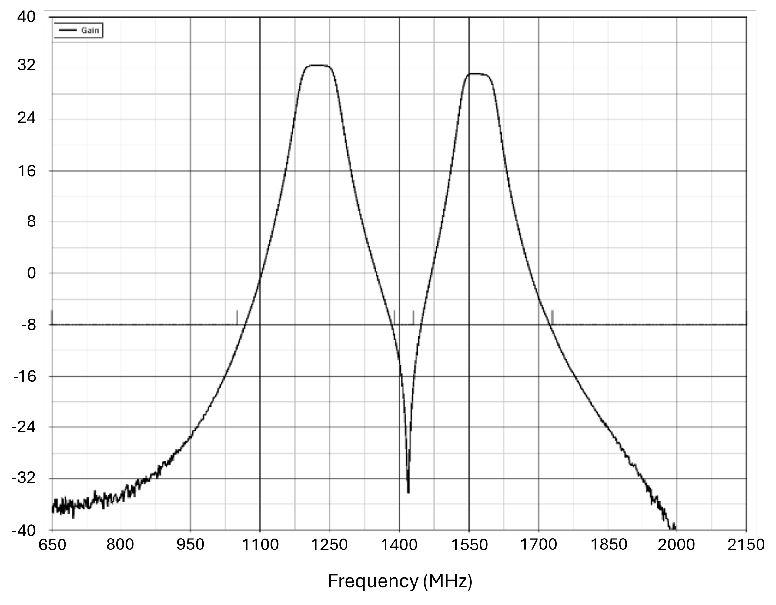
These designs exhibit excellent anti-jam performance by delivering excellent filtering of interference while delivering the best dynamic range possible.
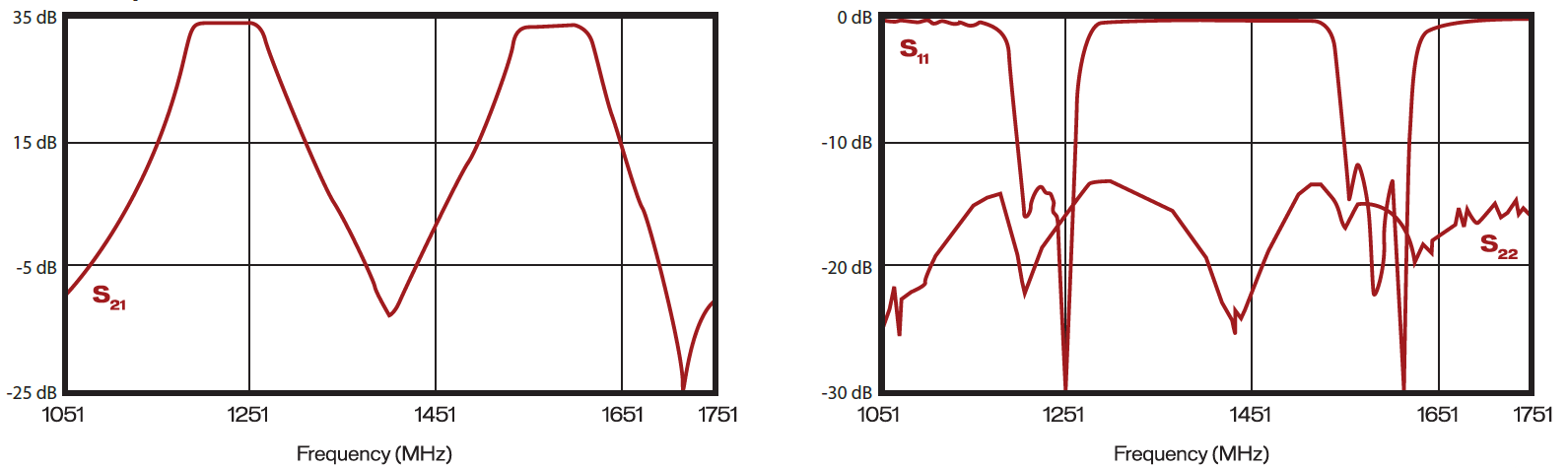
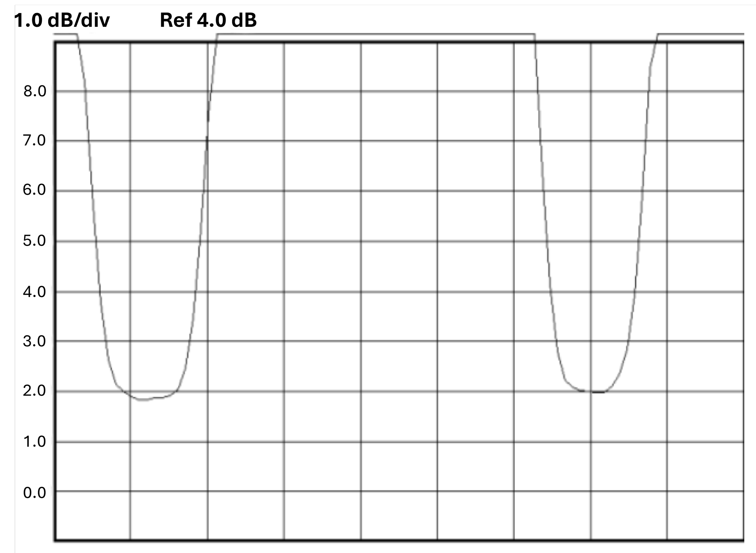
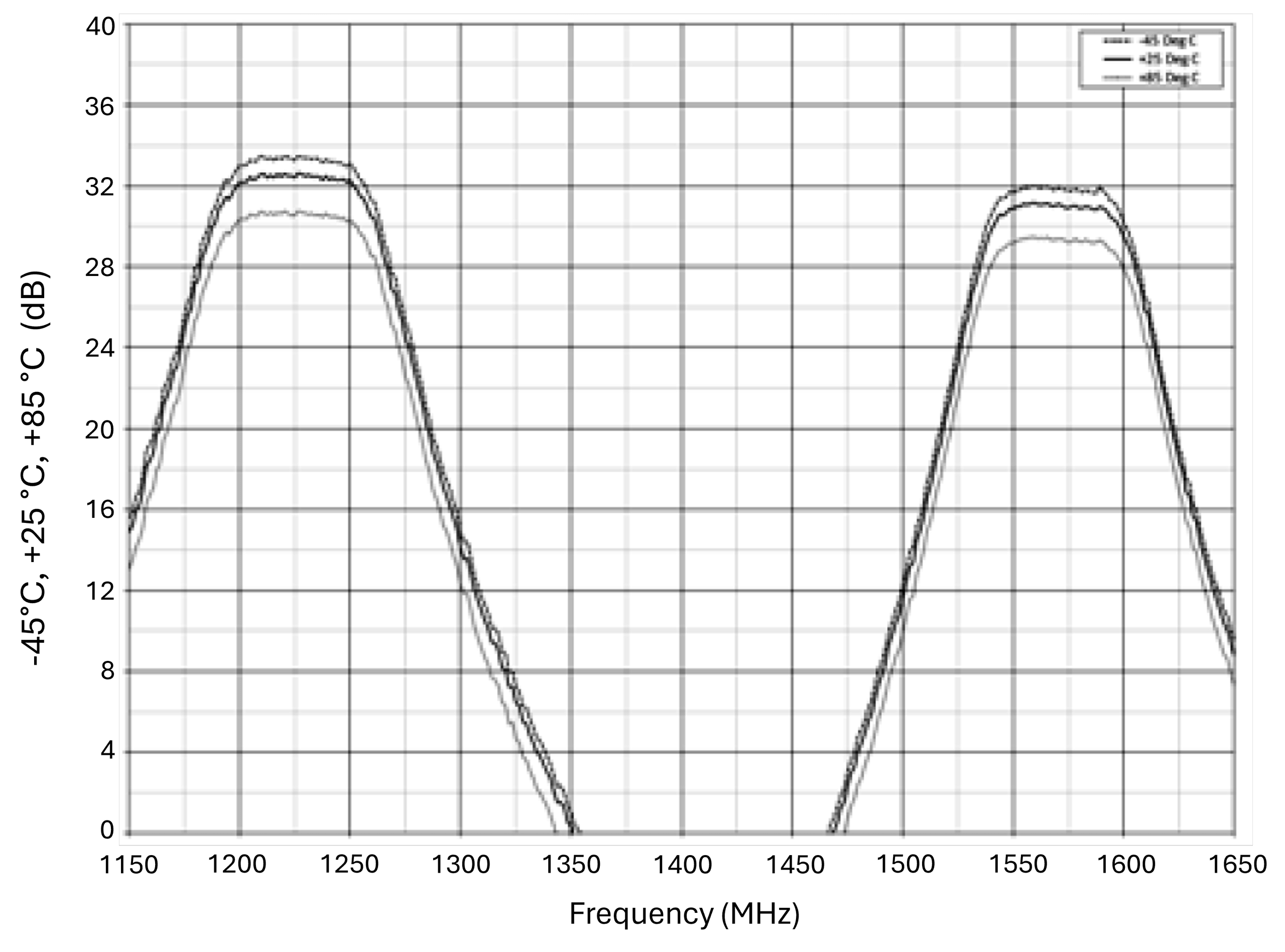
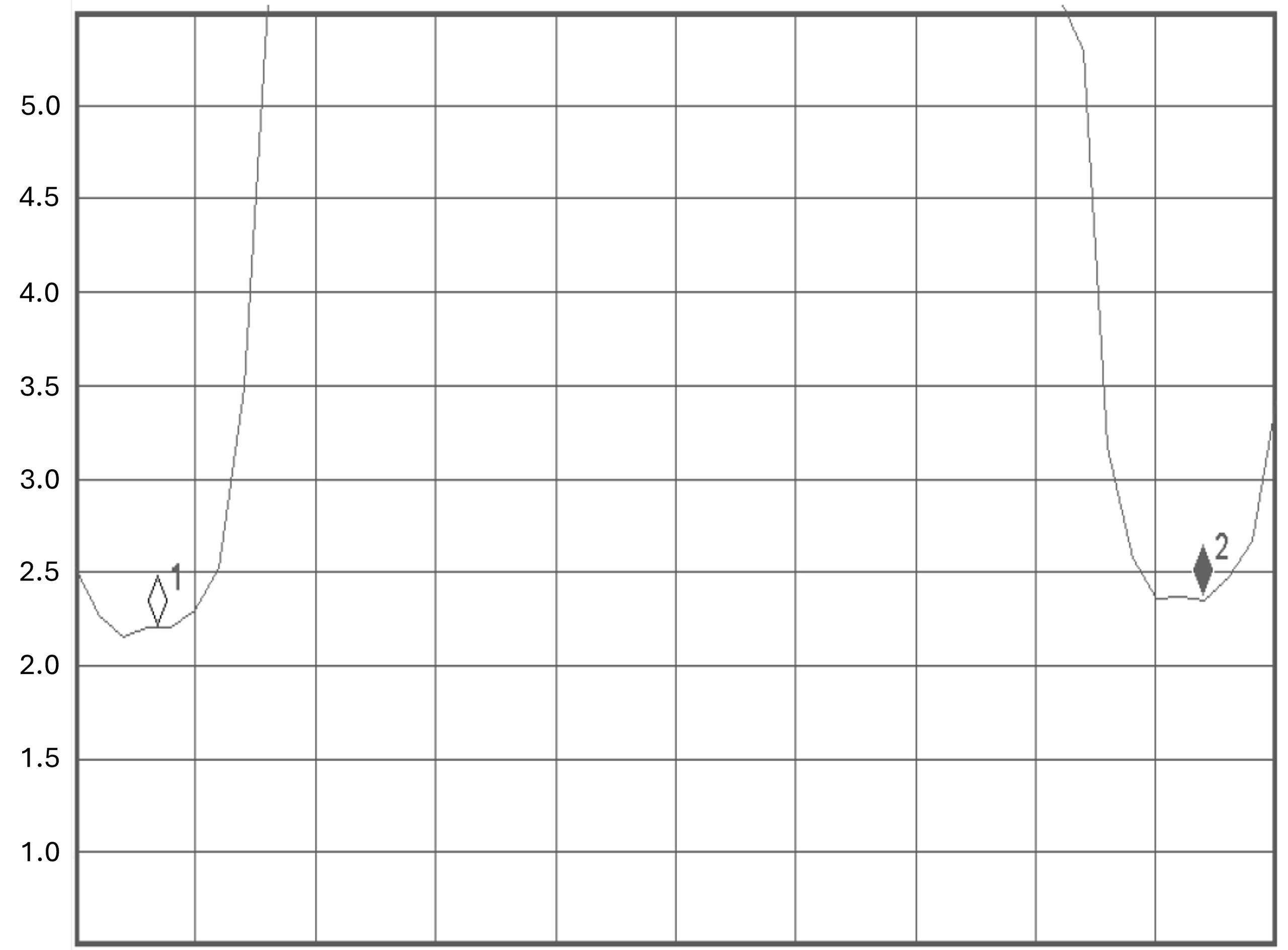
Amplifier Gain (L1/L2) Return Loss (L1/L2)
Spectrum Control Technologies offers a complete line of filtered GPS low-noise amplifiers ideal for applications where high reliability is critical. These filtered low-noise amplifiers are designed to reduce out-of-band interference while achieving high dynamic range.
GPS Dual Band (L1 & L2) 16-32 VDC
| Model | Frequency | Gain (dB) Min. | Noise Figure (dB) Typ. | VSWR | Bandwidth (MHz) | Bias | DC Power (Volts) | Temperature Range |
| 310-025103-012 | 1575.42 MHz (L1) | 14 | 1.8 | 1.5:1 | 30 | Coaxial Bias 5-16 | 16-32 | -40°C to +71°C |
| 1227.60 MHz (L2) | ||||||||
| 310-025103-022 | 1575.42 MHz (L1) | 14 | 1.8 | 1.5:1 | 30 | Ext Bias, MR01 | 16-32 | -40°C to +71°C |
| 1227.60 MHz (L2) | ||||||||
| 310-025105-012 | 1575.42 MHz (L1) | 26 | 1.8 | 1.5:1 | 30 | Coaxial Bias 5-16 | 16-32 | -40°C to +71°C |
| 1227.60 MHz (L2) | ||||||||
| 310-025105-022 | 1575.42 MHz (L1) | 26 | 1.8 | 1.5:1 | 30 | Ext Bias, MR01 | 16-32 | -40°C to +71°C |
| 1227.60 MHz (L2) | ||||||||
| 310-025107-012 | 1575.42 MHz (L1) | 34 | 1.8 | 1.5:1 | 30 | Coaxial Bias 5-16 | 16-32 | -40°C to +71°C |
| 1227.60 MHz (L2) | ||||||||
| 310-025107-022 | 1575.42 MHz (L1) | 34 | 1.8 | 1.5:1 | 30 | Ext Bias, MR01 | 16-32 | -40°C to +71°C |
| 1227.60 MHz (L2) | ||||||||
| 310-025109-012 | 1575.42 MHz (L1) | 45 | 1.8 | 1.5:1 | 30 | Coaxial Bias 5-16 | 16-32 | -40°C to +71°C |
| 1227.60 MHz (L2) | ||||||||
| 310-025109-022 | 1575.42 MHz (L1) | 45 | 1.8 | 1.5:1 | 30 | Ext Bias, MR01 | 16-32 | -40°C to +71°C |
| 1227.60 MHz (L2) |
GPS Dual Band (L1 & L2) 5-16 VDC
| Model | Frequency | Gain (dB) Min. | Noise Figure (dB) Typ. | VSWR | Bandwidth (MHz) | Bias | DC Power (Volts) | Temperature Range |
| 310-025103-011 | 1575.42 MHz (L1) | 14 | 1.8 | 1.5:1 | 30 | Coaxial Bias | 5-16 | -40°C to +71°C |
| 1227.60 MHz (L2) | ||||||||
| 310-025103-021 | 1575.42 MHz (L1) | 14 | 1.8 | 1.5:1 | 30 | Ext Bias, MR01 | 5-16 | -40°C to +71°C |
| 1227.60 MHz (L2) | ||||||||
| 310-025105-011 | 1575.42 MHz (L1) | 26 | 1.8 | 1.5:1 | 30 | Coaxial Bias | 5-16 | -40°C to +71°C |
| 1227.60 MHz (L2) | ||||||||
| 310-025105-021 | 1575.42 MHz (L1) | 26 | 1.8 | 1.5:1 | 30 | Ext Bias, MR01 | 5-16 | -40°C to +71°C |
| 1227.60 MHz (L2) | ||||||||
| 310-025107-011 | 1575.42 MHz (L1) | 34 | 1.8 | 1.5:1 | 30 | Coaxial Bias | 5-16 | -40°C to +71°C |
| 1227.60 MHz (L2) | ||||||||
| 310-025107-021 | 1575.42 MHz (L1) | 34 | 1.8 | 1.5:1 | 30 | Ext Bias, MR01 | 5-16 | -40°C to +71°C |
| 1227.60 MHz (L2) | ||||||||
| 310-025109-011 | 1575.42 MHz (L1) | 45 | 1.8 | 1.5:1 | 30 | Coaxial Bias | 5-16 | -40°C to +71°C |
| 1227.60 MHz (L2) | ||||||||
| 310-025109-021 | 1575.42 MHz (L1) | 45 | 1.8 | 1.5:1 | 30 | Ext Bias, MR01 | 5-16 | -40°C to +71°C |
| 1575.42 MHz (L1) |
For a slightly modified standard design, this handy order guide provides a simple illustration of how to Build you Own Filtered GPS LNA for a wide variety of available options.
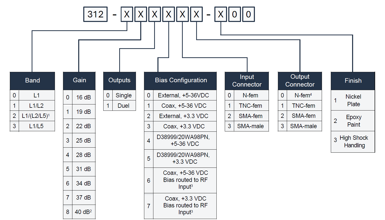
Spectrum’s GPS filtered low-noise amplifier offers flexibility in amplifying either L1 (1575 MHz) or both L1 and L2 (1227 MHz) GPS signals. Through modular assembly and model-specific configurations, this family can be tailored to meet specific requirements for gain, operating voltage, and bias configuration while maintaining a low 1.8 dB (typical) noise figure.
Gain
Noise Figure at +25°C
Spectrum Control's filtered GPS LNAs incorporate DC bias enhancements, including high-power dropping resistors that allow a wider operating voltage range and flexible bias options. Transient Voltage Suppression (TVS) diodes provide enhanced immunity to power supply voltage spikes, while a Zener diode clamp improves the LNA’s protection against excessive input voltages.
Gain Variable over Temperature
Noise Figure at +85°C
Antennas are designed to operate into a 50-ohm resistive load. Spectrum Control’s filtered GPS LNA employs a balanced transistor amplification stage. Most competitors offering products in the L1 frequency band use a single transistor to reduce cost. The balanced amplifier approach provides a broadband match, preserving the stopband attenuation performance of the ceramic filters while allowing the amplifier to maintain stable gain, improved linearity, and consistent impedance matching across the operating band.
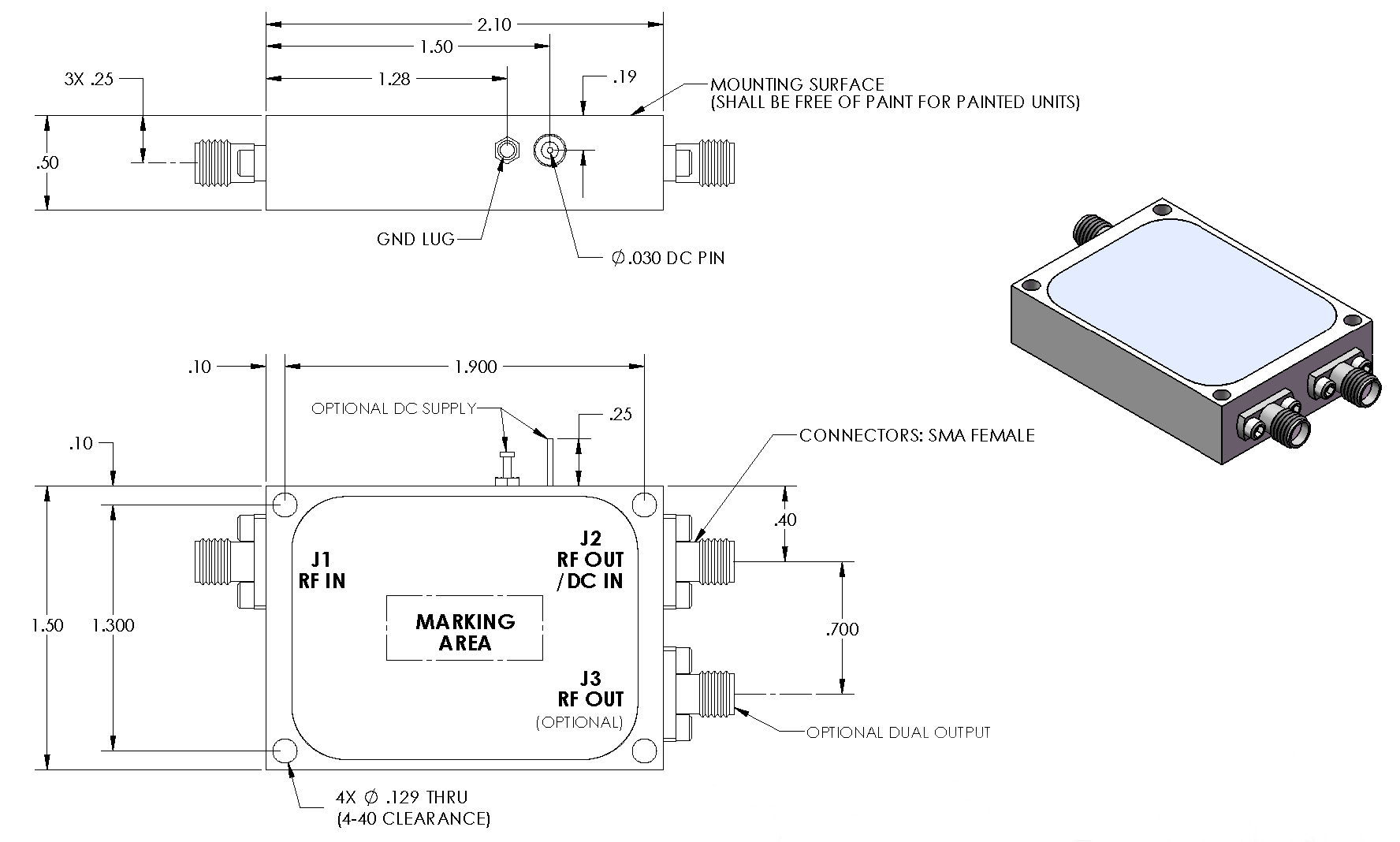
The housing incorporates dual GPS filters with SMA connectors, low-noise amplifiers, a DC supply pin, and a ground lug.
Housing integrates dual GPS filters with TNC connectors and low-noise amplifiers, with DC power applied through the RF input center pin.
The housing incorporates dual GPS filters with SMA connectors, low-noise amplifiers, and a TNC DC bias connector.