

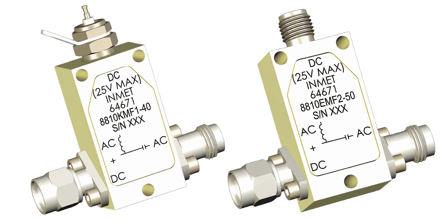
Spectrum Control bias tees with 2.9 mm and 2.4 mm connectors combine DC power and RF signals onto a single coaxial transmission line while maintaining isolation between the RF and DC paths. Their precision interfaces support reliable integration into high-frequency RF and microwave systems.
Engineered for broadband performance, these bias tees provide low insertion loss, low VSWR, and high isolation. They are well suited for powering amplifiers, antennas, detectors, and other active components in test, communications, radar, and aerospace and defense applications.
Bias Tees - Performance & Selection
How it Works
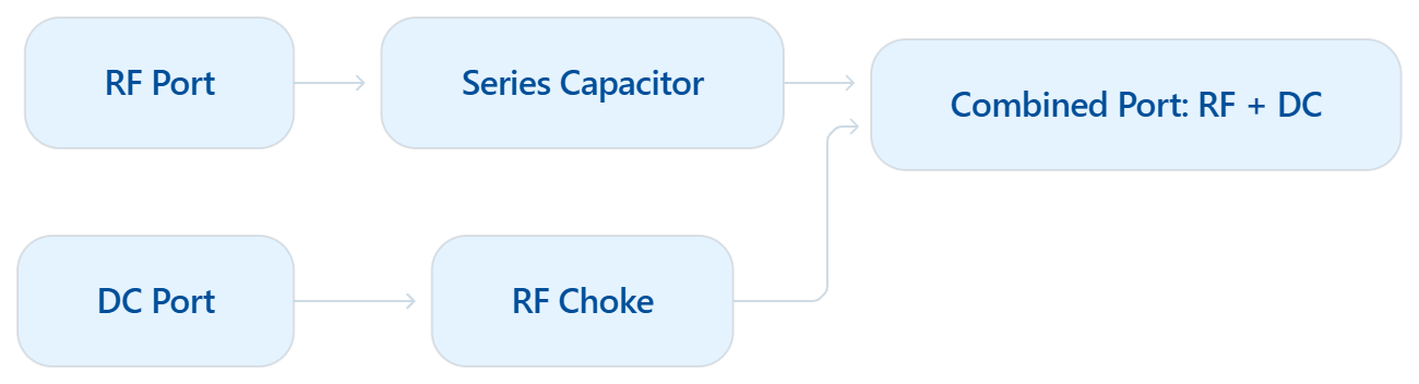
A 2.9 mm or 2.4 mm bias tee uses a capacitor to pass RF while blocking DC and an RF choke to pass DC while blocking RF. The two paths join at the combined port, allowing RF signals and DC power to share one coaxial connection.
Understanding Bias Tees Performance
Selecting a 2.9 mm or 2.4 mm bias tee requires evaluating its RF performance and DC power capabilities across the intended operating range. Key factors include:
-
Frequency Range: Defines the RF frequencies the bias tee can pass.
-
Insertion Loss and VSWR: Indicates the amount of signal strength lost through the RF path.
-
DC Voltage and Current: Measures impedance matching and signal reflections across the frequency range.
-
Isolation: Define the supported voltage and current while indicating how effectively RF energy is blocked from the DC port.
Evaluating these specifications together helps ensure reliable RF transmission and DC power delivery in high-frequency applications.
Why it Matters
Bias tees simplify high-frequency RF systems by delivering power to active components through the signal path. This reduces cabling and component count while precision 2.9 mm and 2.4 mm interfaces help maintain reliable broadband performance.
Part Number |
Freq. Range (GHz) | Insertion Loss (dB) | Current (A) | DC Voltage | Connector Configurations |
| 2.4 mm Connector Type | |||||
| 8810E | 50 kHz - 50 | 0.50 - 4.00 | 0.15 | 25 max. |
M/F, M/M,
F/F, F/M
|
| 2.9 mm Connector Type | |||||
| 8810K | 50 kHz - 40 | 3.00 | 0.15 - 0.75 | 25 max. |
M/F, M/M,
F/F, F/M
|
| 8812K | 12 kHz - 40 | 1.5 - 3.00 | 0.15 | 16 max. |
M/F, M/M,
F/F, F/M
|
Bias Tees - How they Work
Supporting RF Transmission and DC Bias Through Precision Coaxial Interfaces.
In 2.9 mm and 2.4 mm bias tees, the RF signal travels through a capacitive path that passes the operating frequencies while preventing DC from reaching the RF-only port.
The DC input follows a separate inductive path. An RF choke carries the required bias power toward the combined port while restricting RF signals from traveling back to the DC power source.
These paths converge at the combined port, where RF and DC share the same precision coaxial connection. This arrangement allows power to reach active microwave components while maintaining signal integrity and reducing the need for additional cabling.
- Series capacitor: Passes RF signals while preventing DC from entering the RF-only port
- RF Choke: Carries DC bias to the combined port while restricting RF energy
- Combined Port: Carries RF and DC through a single 2.9 mm or 2.4 mm connection

Typical Applications
-
mmWave test and measurement
-
Broadband amplifier biasing
-
High-frequency radar systems
-
Electronic warfare equipment
-
SATCOM payloads and terminals
-
Microwave instrumentation
- Optical modulators and photodiodes
- Semiconductor device characterization
Why Choose Spectrum Control?
-
Precision 2.9 mm and 2.4 mm interfaces
-
Broadband frequency coverage
-
Low insertion loss
-
Low VSWR
-
High RF-to-DC isolation
-
Multiple voltage and current ratings
- Compact coaxial construction
- Engineering and customization support