FILTERED CONNECTOR EXPRESSTM
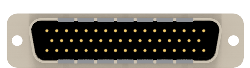
D-Sub Filtered Connectors
Specify a custom filtered connector to your requirements.
Specs to finished prototypes or production volumes in 8 weeks!
Use the online configurator below to design a custom EMI-filtered D-Sub connector with integrated Pi and C circuit protection.
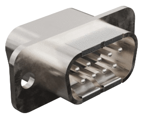
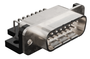
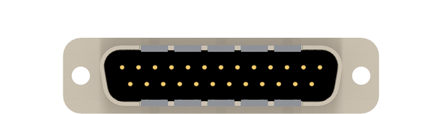
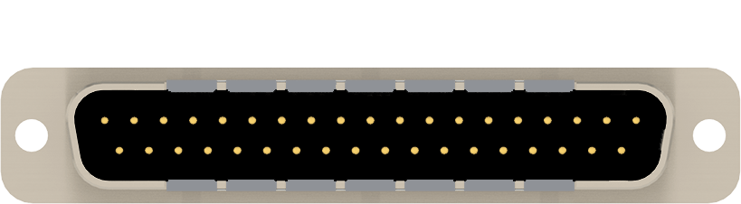
Choose from five shell sizes, 9, 15, 25, 37, and 50 pin, in straight and right-angle configurations.
Termination options include pin-to-PCB, pin-to-solder-cup, and socket-to-solder-cup.
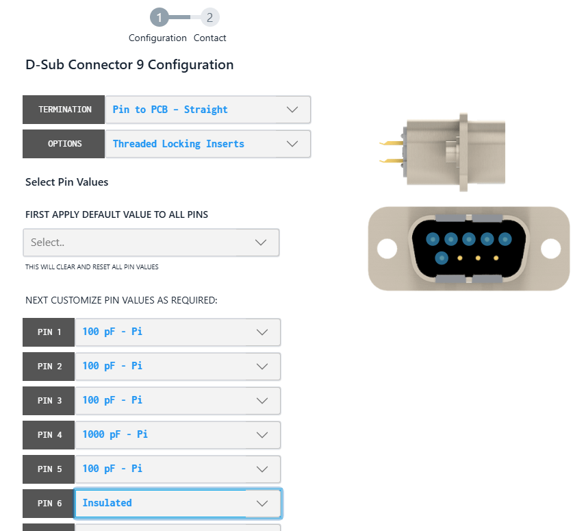
Configure Your Custom Filtered Connector
Get started by selecting your shell size.


Instructions
1. Select your connector to get started
2. Choose your termination
- Pin to PCB – Straight
- Pin to PCB - Right Angle
- Pin to Solder Cup – Straight
- Socket to Solder Cup - Straight
3. *Choose your options
- Threaded locking inserts
- Stand-off with board lock
- Grounding bracket
- Grounding bracket with board lock
*Available options vary by termination and will appear in the dropdown once the termination type has been selected.
4. Configure circuit values for each pin
- 100 pF – Pi
- 310 pF – Pi
- 1000 pF – Pi
- 2500 pF – Pi
- 4000 pF – Pi
- 1000 pF - C
- 5000 pF - C
- Insulated Line
5. Submit for quote
Click the submit button to send your specs.
Please note the two check boxes under Contact Me below before you click.
![]() Tick the first box to indicate you have a custom drawing or other configuration requests (cost and lead time may be affected).
Tick the first box to indicate you have a custom drawing or other configuration requests (cost and lead time may be affected).
![]() Tick the second box to inquire about technical support.
Tick the second box to inquire about technical support.
Product Overview
Spectrum Control has applied its 50 years of experience in managing EMI/EMC to create an expedited approach to building custom connectors for military and aerospace applications. We can now deliver custom high performance D-sub filtered connectors to your specifications in only 8 weeks with no NRE.
-
Configurable connector – with circuits/values for mixed signals in a single d-sub connector package
-
Quick turnaround – for quick prototyping or production units, from specs to finished products in 8 weeks; no NRE
-
Superior EMI filtering – Spectrum Control manufactured custom coaxial tubular capacitors facilitate superior broadband performance, particularly at high frequencies, versus chip on board (COB) and chip in seal versions
-
Soldered construction – for better high-frequency performance over mechanical designs
-
Large capacitance pin-to pin-ratio range – for optimized performance in mixed signal applications in a single package
Filter Designation: per insertion loss performance graphs
| Filter Designation | Filter Circuit | Capacitance | ||
| Value | Tolerance | |||
| J | Pi | 100 pF | +100 -0% | |
| A | 310 pF | +25% | ||
| C | 1000 pF | +150 -0% | ||
| K | 2500 pF | +100 -0% | ||
| E | 4000 pF | +100 -0% | ||
| B | C | 1000 pF | +100 -0% | |
| D | 5000 pF | +100 -0% | ||
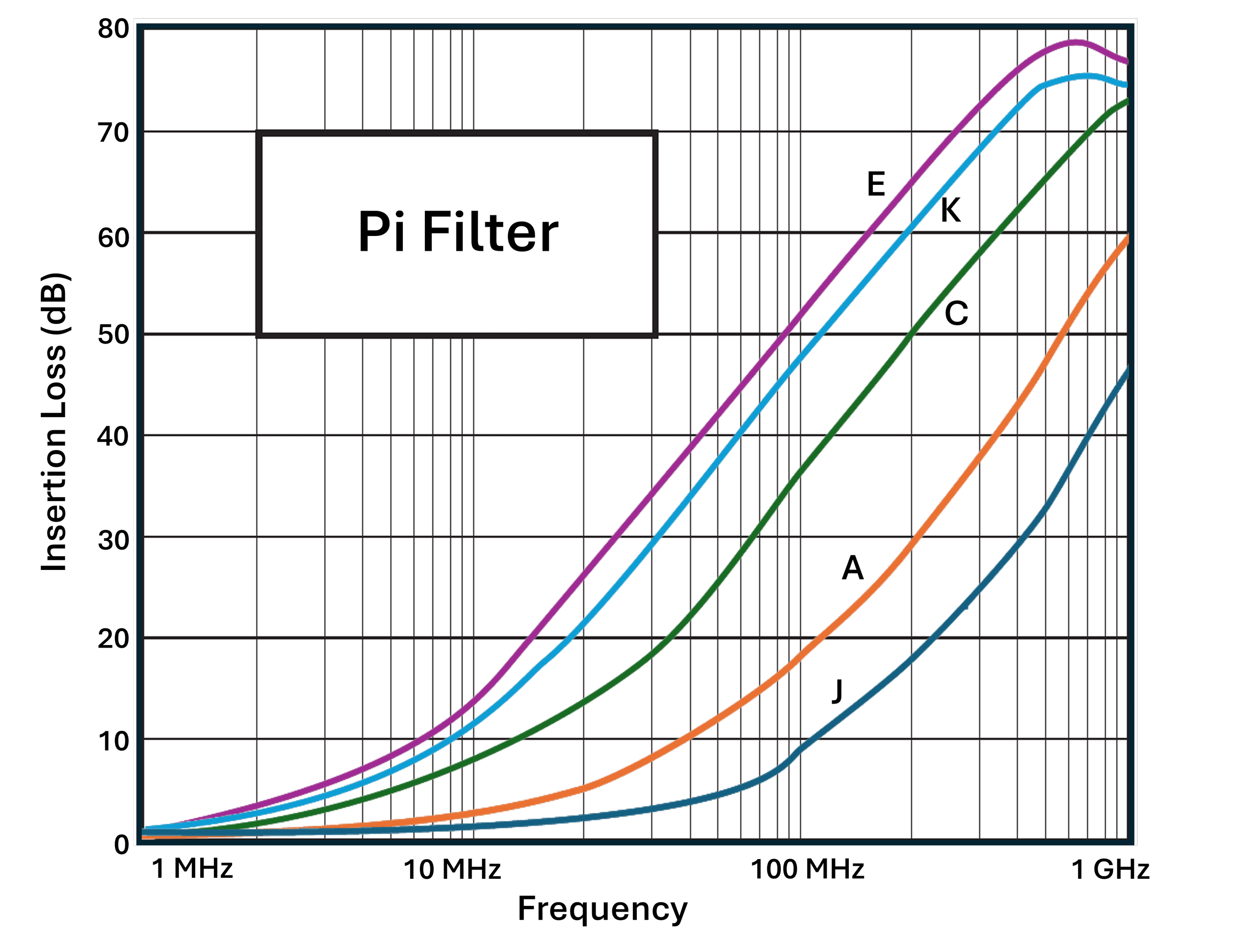
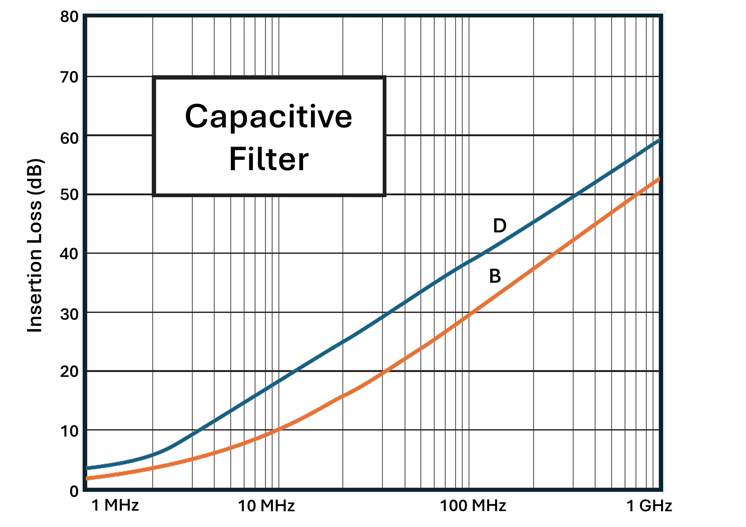
Performance graphs typical for configurable connectors.
Quality Assurance
All EMI filtered connectors undergo extensive testing to ensure that all products meet specification requirements. Many tests are performed 100% by computer-controlled test sets, including capacitance, dissipation factor, dielectric withstanding voltage, and Insulation resistance as routine. Others are tested on a sample basis as applicable. Test plans can be configured to specific customer requirements.
Qualification/special testing - Spectrum has a fully qualified test laboratory and can provide additional acceptance testing upon the customer’s request. This could be a one-time qualification exercise or ongoing periodic testing.
Test Specifications
-
All test conditions at 25±5°C & 30-50% relative humidity
-
DF at 1.0 Vrms @ 1 KHz ±1%
-
IL per MIL-STD-220, no load condition
-
IR per MIL-STD-202, Method 302
-
DWV per MIL-STD-202, Method 302, 1-5 sec. 50 mA max.
-
CAP. per MIL-STD-202, Method 305, 1.0 VRMS @ 1KHz. ±1%
STEP Files
Download STEP files for Spectrum Control configurable D-Sub connectors to simplify mechanical integration and accelerate your design process. Compatible with most major CAD platforms for seamless incorporation into your assemblies.
| Pin Count | Termination | Option | Download |
| 9-Pin | Pin to PCB - straight | None | STEP File |
| 9-Pin | Pin to PCB - straight | Threaded Locking Inserts | STEP File |
| 9-Pin | Pin to PCB - straight | Stand-off with Board Lock | STEP File |
| 9-Pin | Pin to PCB - right angle | None | STEP File |
| 9-Pin | Pin to PCB - right angle | Grounding Bracket | STEP File |
| 9-Pin | Pin to PCB - right angle | Grounding Bracket with Board Lock | STEP File |
| 9-Pin | Pin to solder cup | None | STEP File |
| 9-Pin | Pin to solder cup | Threaded Locking Inserts | STEP File |
| 9-Pin | Socket to solder cup | None | STEP File |
| 9-Pin | Socket to solder cup | Threaded Locking Inserts | STEP File |
| 15-Pin | Pin to PCB - straight | None | STEP File |
| 15-Pin | Pin to PCB - straight | Threaded Locking Inserts | STEP File |
| 15-Pin | Pin to PCB - straight | Stand-off with Board Lock | STEP File |
| 15-Pin | Pin to PCB - right angle | None | STEP File |
| 15-Pin | Pin to PCB - right angle | Grounding Bracket | STEP File |
| 15-Pin | Pin to PCB - right angle | Grounding Bracket with Board Lock | STEP File |
| 15-Pin | Pin to solder cup | None | STEP File |
| 15-Pin | Pin to solder cup | Threaded Locking Inserts | STEP File |
| 15-Pin | Socket to solder cup | None | STEP File |
| 15-Pin | Socket to solder cup | Threaded Locking Inserts | STEP File |
| 25-Pin | Pin to PCB - straight | None | STEP File |
| 25-Pin | Pin to PCB - straight | Threaded Locking Inserts | STEP File |
| 25-Pin | Pin to PCB - straight | Stand-off with Board Lock | STEP File |
| 25-Pin | Pin to PCB - right angle | None | STEP File |
| 25-Pin | Pin to PCB - right angle | Grounding Bracket | STEP File |
| 25-Pin | Pin to PCB - right angle | Grounding Bracket with Board Lock | STEP File |
| 25-Pin | Pin to solder cup | None | STEP File |
| 25-Pin | Pin to solder cup | Threaded Locking Inserts | STEP File |
| 25-Pin | Socket to solder cup | None | STEP File |
| 25-Pin | Socket to solder cup | Threaded Locking Inserts | STEP File |
| 37-Pin | Pin to PCB - straight | None | STEP File |
| 37-Pin | Pin to PCB - straight | Threaded Locking Inserts | STEP File |
| 37-Pin | Pin to PCB - straight | Stand-off with Board Lock | STEP File |
| 37-Pin | Pin to PCB - right angle | None | STEP File |
| 37-Pin | Pin to PCB - right angle | Grounding Bracket | STEP File |
| 37-Pin | Pin to PCB - right angle | Grounding Bracket with Board Lock | STEP File |
| 37-Pin | Pin to solder cup | None | STEP File |
| 37-Pin | Pin to solder cup | Threaded Locking Inserts | STEP File |
| 37-Pin | Socket to solder cup | None | STEP File |
| 37-Pin | Socket to solder cup | Threaded Locking Inserts | STEP File |
| 50-Pin | Pin to PCB - straight | None | STEP File |
| 50-Pin | Pin to PCB - straight | Threaded Locking Inserts | STEP File |
| 50-Pin | Pin to PCB - straight | Stand-off with Board Lock | STEP File |
| 50-Pin | Pin to PCB - right angle | None | STEP File |
| 50-Pin | Pin to PCB - right angle | Grounding Bracket | STEP File |
| 50-Pin | Pin to PCB - right angle | Grounding Bracket with Board Lock | STEP File |
| 50-Pin | Pin to solder cup | None | STEP File |
| 50-Pin | Pin to solder cup | Threaded Locking Inserts | STEP File |
| 50-Pin | Socket to solder cup | None | STEP File |
| 50-Pin | Socket to solder cup | Threaded Locking Inserts | STEP File |