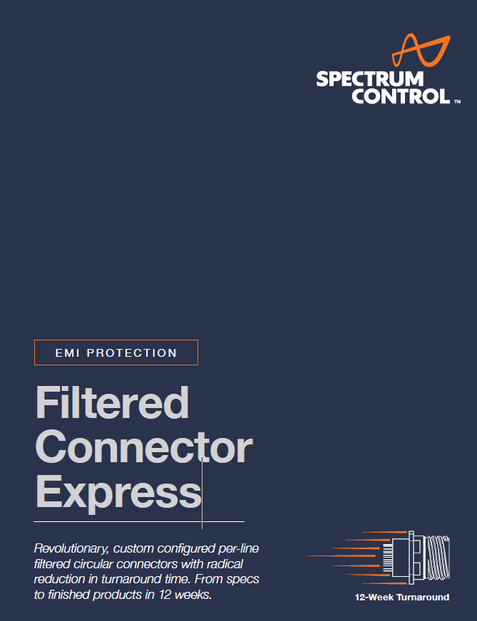
FILTERED CONNECTOR EXPRESSTM
Filtered Circular Connectors
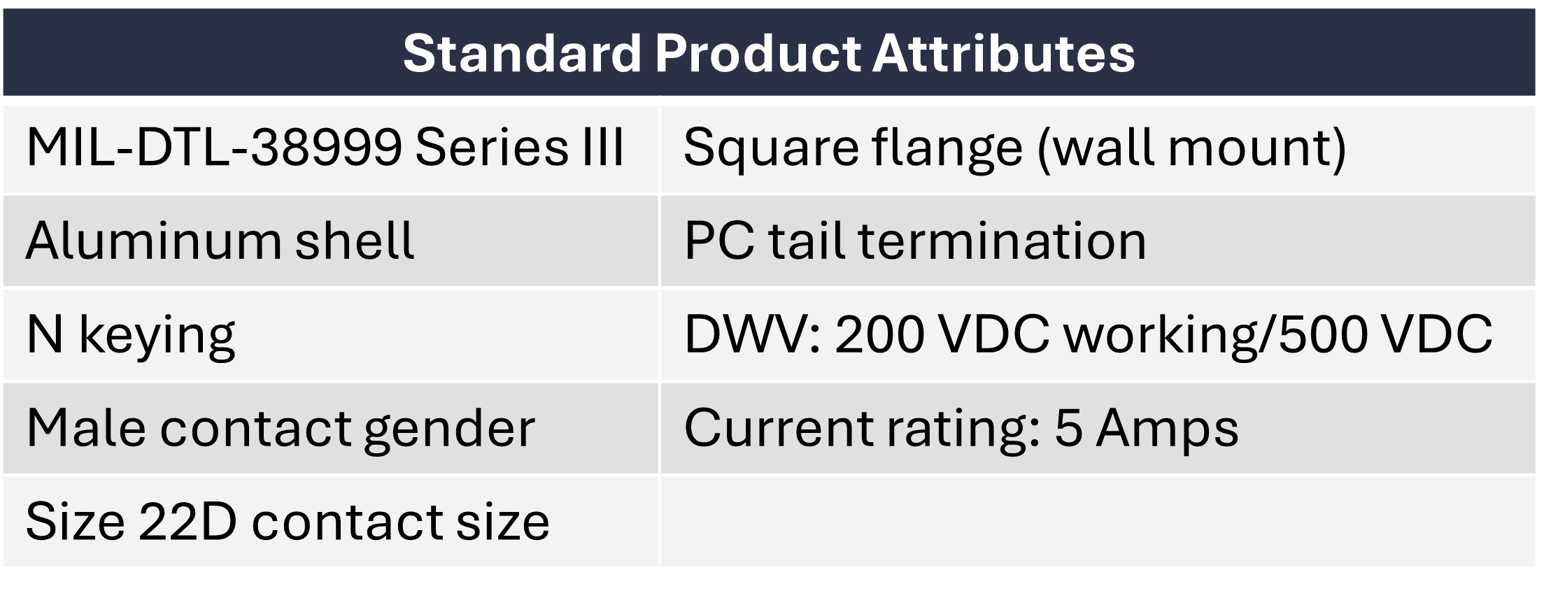
Specify an EMI-filtered, MIL-DTL 38999-compatible connector to your requirements.
Go from specs to finished prototypes or production volumes in 12 weeks!
Use the online configurator below to design a custom EMI-filtered connector with integrated Pi and C circuit protection.
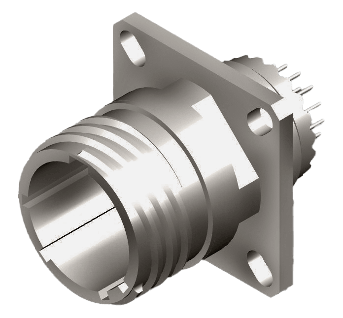
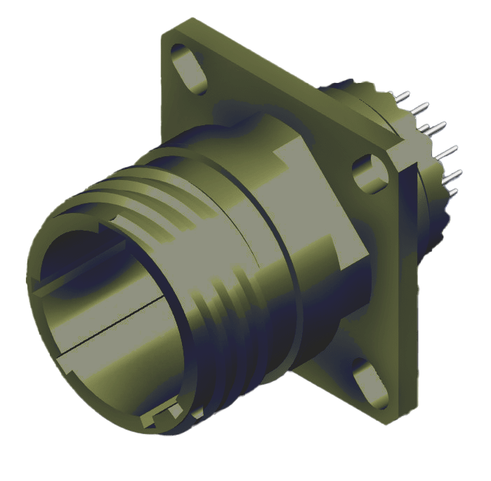
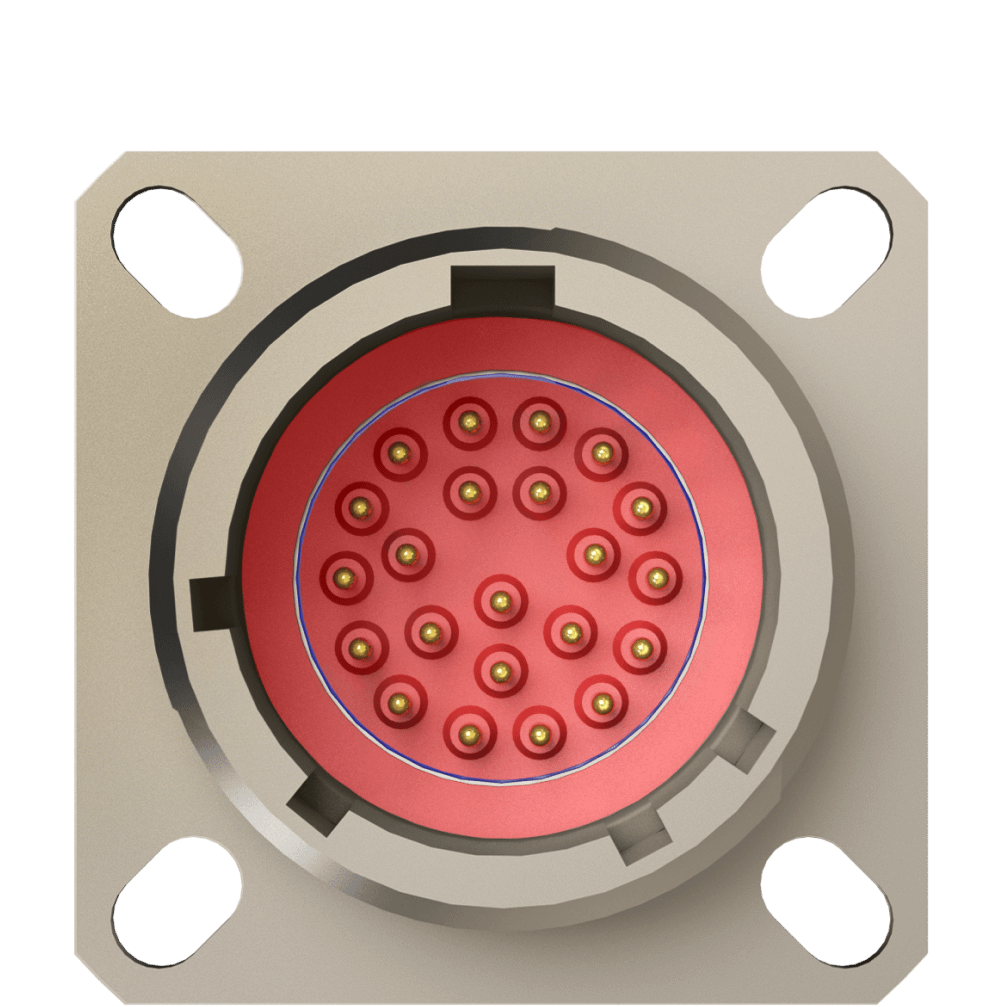
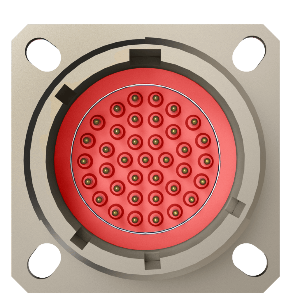
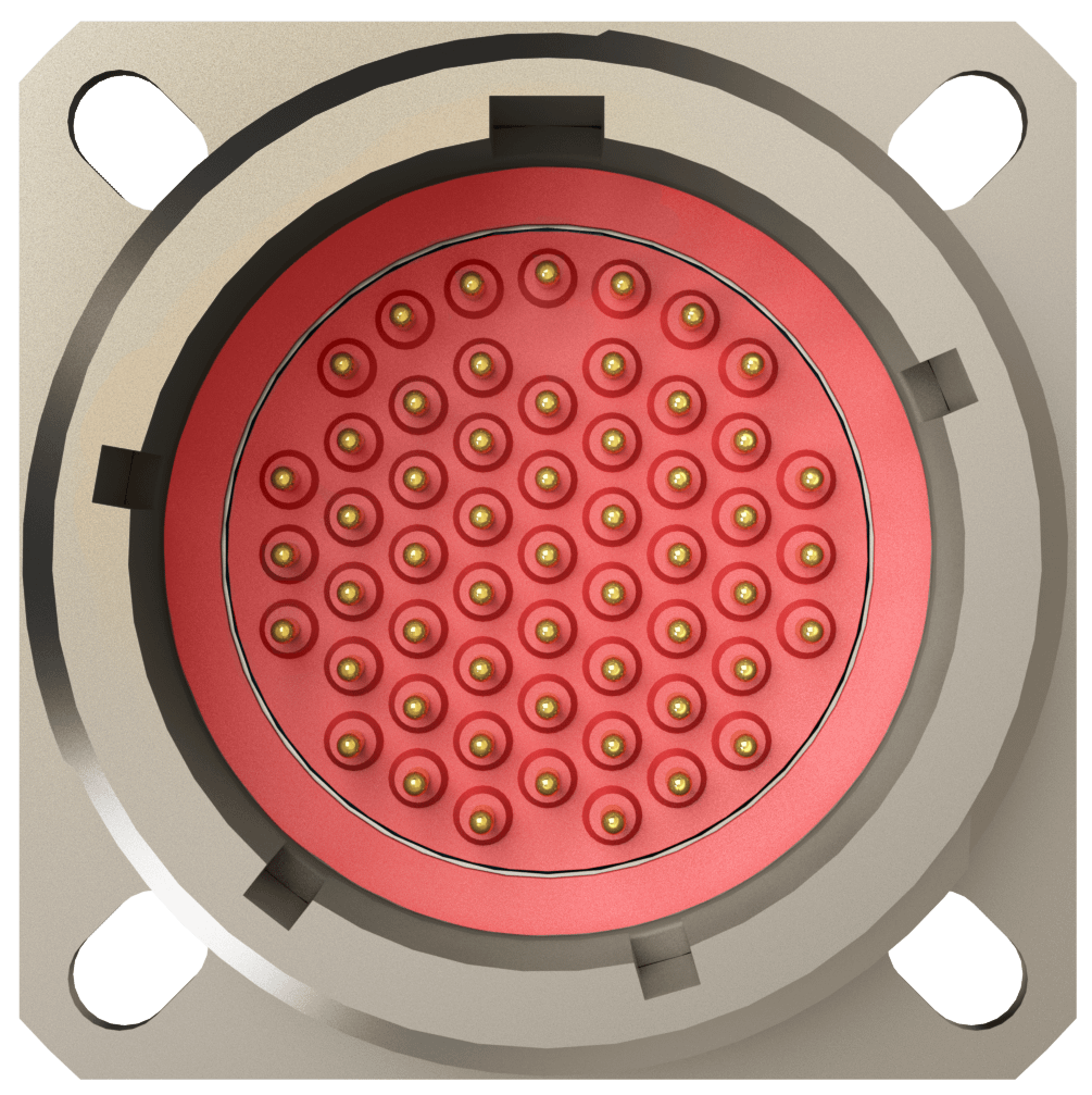
Select from two surface finishes: Nickel and ODCAD and 3 pin configurations: 13-35, 15-35, 17-35
Overview
Spectrum Control has applied its 50 years of experience in managing EMI/EMC to create an expedited approach to building custom connectors for military and aerospace applications. We can now deliver custom filtered connectors to your specifications in only 12 weeks with no NRE.
-
Configurable connector – with circuits/values for mixed signals in a single circular connector package
-
Quick turnaround – for quick prototyping or production units, from specs to finished products in 12 weeks; no NRE
-
Superior EMI filtering – combination of a planar and substrate filtering for superior performance versus chip-on-board (COB) or chip-in-seal versions
-
Soldered construction – for better high-frequency performance over mechanical designs
-
Large capacitance pin-to pin-ratio range – for consistent performance with power and signal filtering in a single package
-
Aluminum shell – for rugged environmental and/or weight sensitive applications
*Additional custom configurations available, but may impact cost and lead time.
Performance vs. Lead Time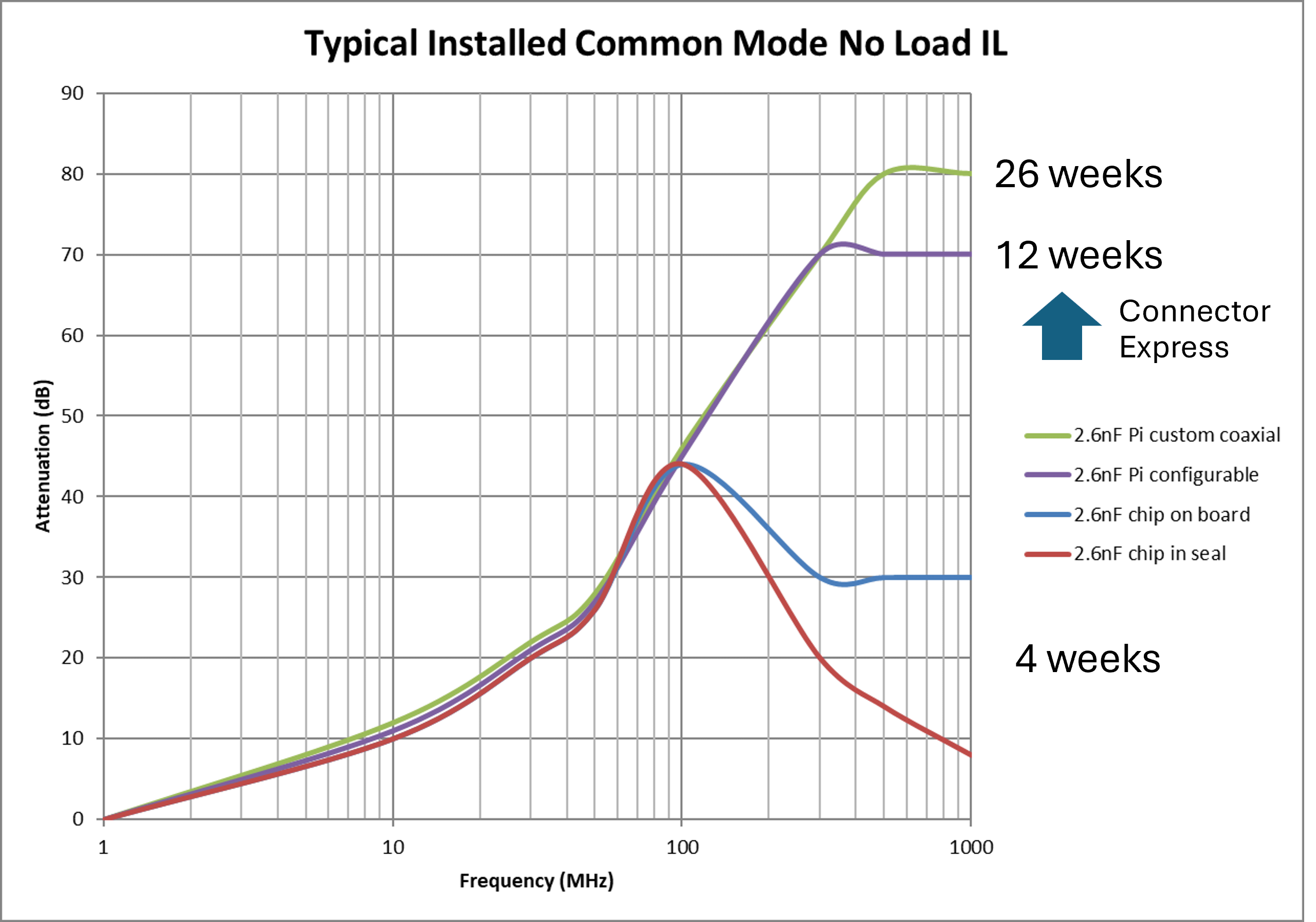
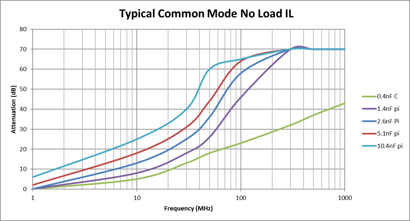
Connector Express Circuit Options
Quality Assurance
All EMI filtered connectors undergo extensive testing to ensure that all products meet specification requirements. Many tests are performed 100% by computer-controlled test sets, including capacitance, dissipation factor, dielectric withstanding voltage, and Insulation resistance as routine. Others are tested on a sample basis as applicable. Test plans can be configured to specific customer requirements.
Qualification/special testing - Spectrum has a fully qualified test laboratory and can provide additional acceptance testing upon the customer’s request. This could be a one-time qualification exercise or ongoing periodic testing.
Test Specifications
-
All test conditions at 25±5°C & 30-50% relative humidity
-
DF at 1.0 Vrms @ 1 KHz ±1%
-
IL per MIL-STD-220, no load condition
-
IR per MIL-STD-202, Method 302
-
DWV per MIL-STD-202, Method 302, 1-5 sec. 50 mA max.
-
CAP. per MIL-STD-202, Method 305, 1.0 VRMS @ 1KHz. ±1%
Resources
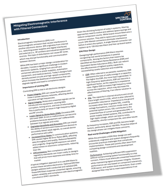
Download Whitepaper
Mitigating EMI with Filtered Connectors
Designed by engineers for engineers! Here is the technical data behind this novel approach to filtered connectors.
Download Brochure
Configurable Filtered Connector Express
Download STP files
Insert configuration - 13-35
Insert configuration - 15-35
Insert configuration - 17-35
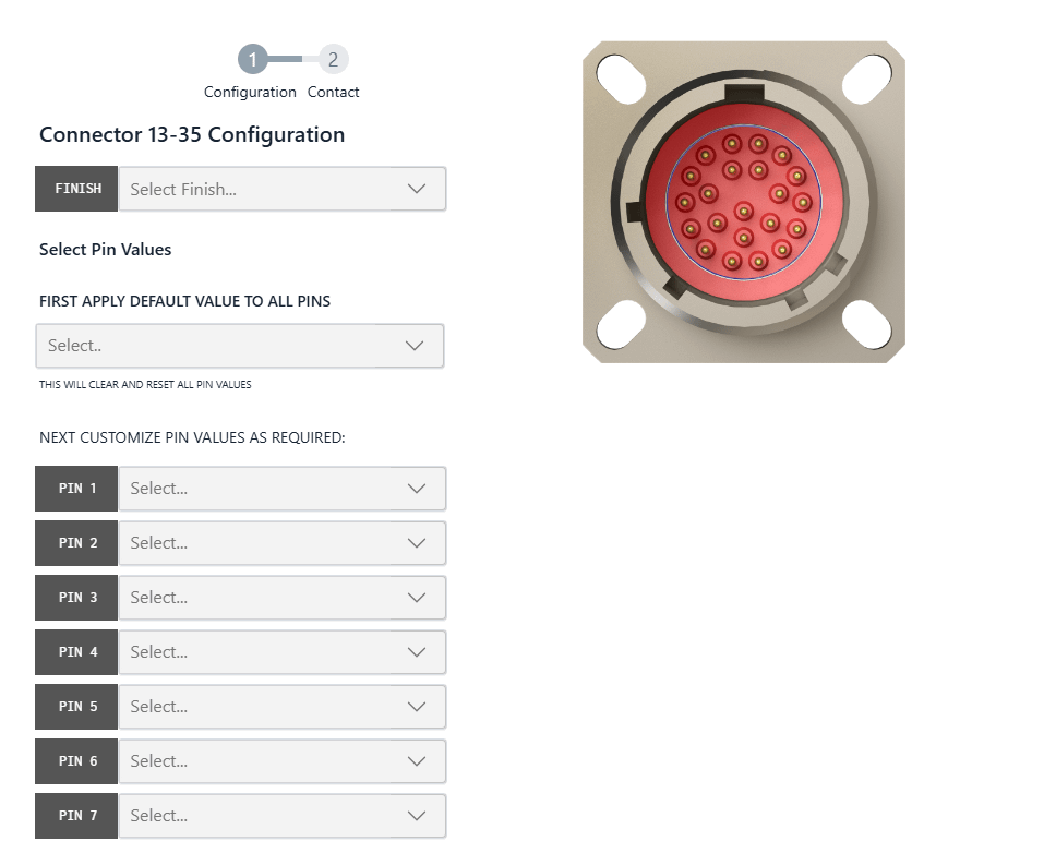
Configure Your Custom Connector
Instructions
1. Select your connector to get started
2. Choose your surface finish
- Nickel
- Olive Drab Cadmium
3. Choose your insert configuration
- 13-35
- 15-35
- 17-35
4. Configure circuit values for each pin
- 400 pF – C
- 1400 pF – Pi
- 2600 pF – Pi
- 5100 pF – Pi
- 10400 pF – Pi
- Ground Line
5. Submit
- TO DISCUSS PROJECT & PRICING
- FOR TECHNICAL ASSISTANCE*