Introduction to Saw Filter Design
Introduction to Saw Filter Design
Spectrum Control offers a wide range of high quality standard and custom Surface Acoustic Wave (SAW) product solutions. Spectrum Control believes in a flexible approach and possesses high volume capability and world wide support.
In theory, an ideal filter would possess no loss, an instantaneous transition from the pass band to the stop band, infinite stop band attenuation, no signal distortion introduced by the filter and have very small size and cost. In reality, many tradeoffs need to be considered when selecting a filter for a system design. An advantage of SAW filter technology is the realization of parts with reduced size and weight; hence, a lower cost than other filter technologies since the same type of process equipment that IC manufacturers rely upon can be adapted for use to manufacture a SAW product.
This white paper will present some general SAW theory and performance as well as applications to help guide the RF designer.

SAW Fundamentals
1. Overview
A SAW filter operates by converting electrical energy into acoustic or mechanical energy on a piezoelectric material. This piezoelectric effect is initiated by introducing two interdigital transducers. The input transducer creates acoustic waves from the incident electrical signal and the output transducer receives the acoustic waves (Figure 1a), converting them back into electrical energy. These waves are generated equally in both the +X and -X direction by the transducer and this is known as a bidirectional transversal filter. Since the desired wave to be converted is only ½ of the total (+X direction) a loss of 3 dB is observed; for the input and output transducer together, the resulting processed signal will possess an insertion loss of 6 dB (Figure 1b).
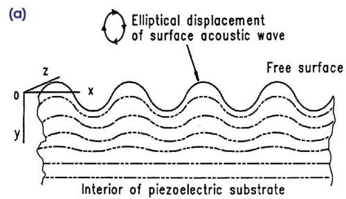
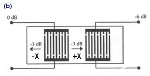
Figure 1:
(a)Diagram of a Surface Acoustic Wave travelling on substrate surface. (Courtesy of C.K. Campbell, Ph.D.: Supplemental notes on lectures on SAW Devices, 1985)
(b)Bi-directional operation of a typical transversal device with equal SAW generation in -X and +X directions. (Courtesy of ‘SAW fundamentals’, SAWTek, 2/15/2001, p. 2)
Each transducer is composed of periodic interdigital electrodes connected to two bus bars as shown in Figure 2. The bus bars are connected to the electrical source or load. A single interdigital electrode will act as an acoustic source or detector, and the amplitude will be determined by the electrode length, and the phase will be given by the electrode’s position. The wavelength (λ) of the electrodes and neighboring spaces determines the operating frequency for the SAW device.
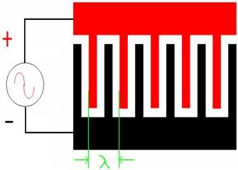
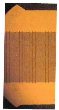
Figure 3: Diagram of a basic transducer and a photograph. Golden colored area represents the patterned metal against the piezoelectric substrate (Courtesy of M. Schweyer, Spectrum Control)
With this general arrangement, the acoustic energy, concentrated at the crystal’s surface, is easily accessible for signal processing.
2. Piezoelectric Materials Used for SAW Product
Table 1 show the most common materials used for the manufacture of SAW product. Each material possesses qualities that work best for a certain segment of each SAW filter type.
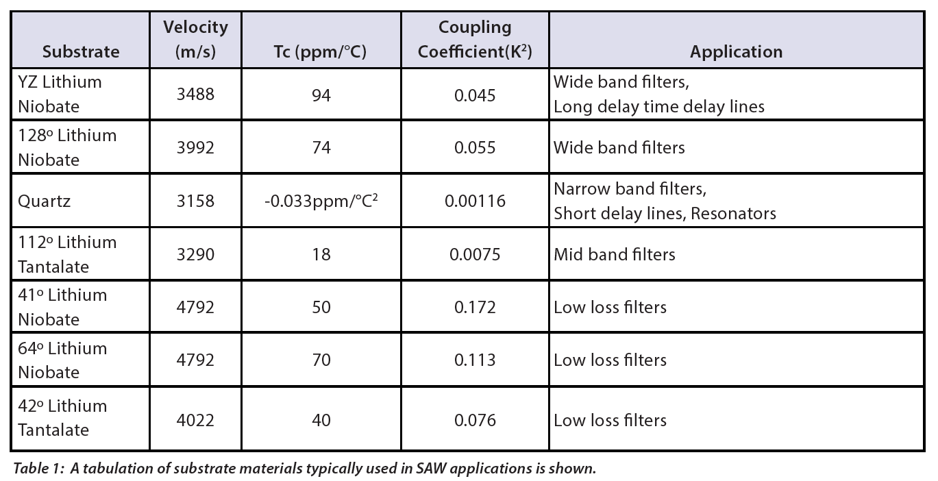

The Tc value, temperature coefficient, represents the shift in center frequency versus the operating temperature of the SAW component. Except for the Quartz substrate, the filter will shift upwards at lower temperatures and downwards at higher temperatures in a linear fashion. These shifts are accounted for in the design of the SAW by adding a temperature
shift component to the pass band requirement and subtract it from the stop band requirement.
For quartz, the temperature shift is downwards parabolic with a turnover temperature value where the temperature coefficient is zero. The turnover temperature can be set by using quartz with different cut angles for best overall performance over the customer’s temperature range.
The coupling coefficient (K2) represents how efficient the material is at producing an acoustic wave. Materials with larger K2 values produce stronger acoustic waves and generally possess less loss per unit of delay (substrate length). This allows for a wider filter or longer delay line.
3. Transversal SAW Devices
Transversal SAW devices are generally designed using a Finite Impulse Response (FIR) technique with the Fourier transform. The transducer is conceived in the time response. When transformed to the frequency response, the general filter shape is produced. Figure 3 shows a few examples of this process.
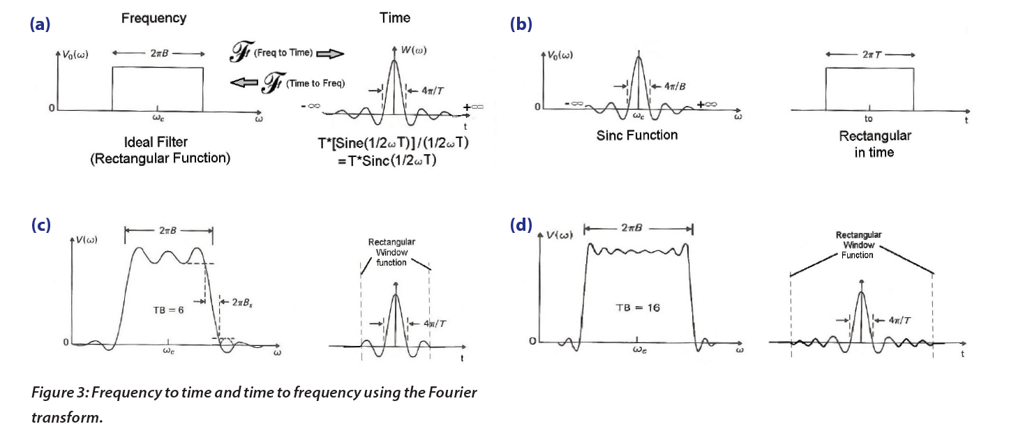
(a) A ‘Perfect’ (desired) brick wall filter or Rectangular function in frequency transforms to a perfect Sinc (Sine(X)/X) Function in time. This results in an impractical transducer since it would possess an infinite length.
(b) Conversely, a Rectangular function in time transforms into a Sinc function in frequency.
The coupling coefficient (K2) represents how efficient the material is at producing an acoustic wave. Materials with larger K2 values produce stronger acoustic waves and generally possess less loss per unit of delay (substrate length). This allows for a wider filter or longer delay line.
(c) If truncated in time with a window function, a filter in frequency will result with ripples in the passband and reject band and sloped skirts.
(d) Truncating further away from the main time lobe of the Sinc produces a ‘better’ transducer, but it will be longer. (With aid from ‘Surface-Wave Devices for Signal Processing’, by David P. Morgan, Elsevier 1991, p. 194)
The desired time response is sampled at regular intervals to create a transducer with the appropriately spaced electrodes per Figure 4.
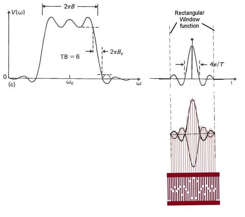
Figure 4: Once the desired time response is obtained, it is reflected about the time axis. This result is sampled at regular intervals, producing a representation of the necessary response in the transducer. (With aid from ‘Surface-Wave Devices for Signal Processing’, by David P. Morgan, Elsevier 1991, p. 190)
This transducer is paired with another to receive its launched SAW and the receiver transducer may perform more processing to the response if needed, producing a typical filter as shown in Figure 5.
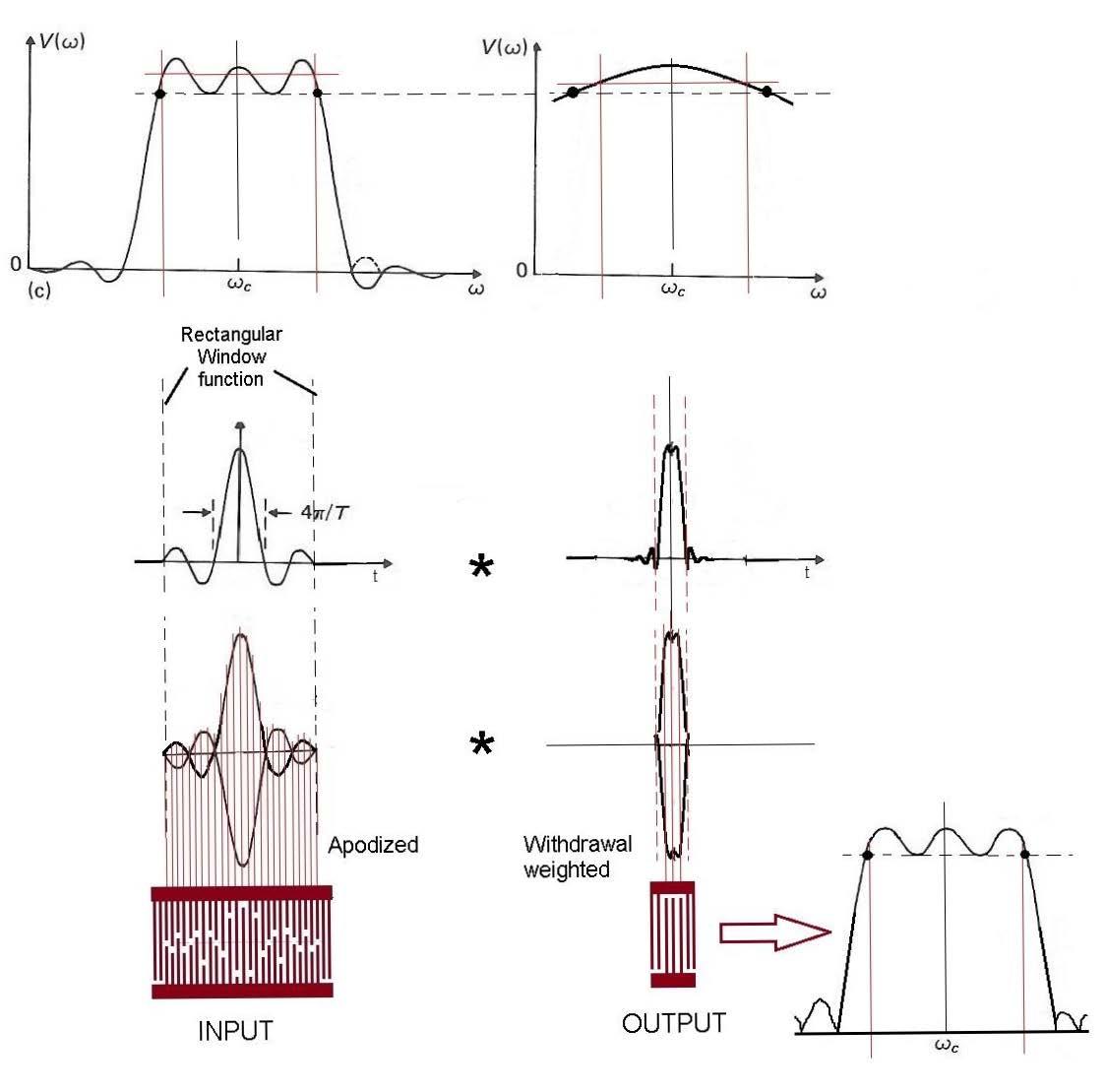
Figure 5: A receiver transducer is created in a similar manner to form the completed filter; typically the same sampling rate is used. (With aid from ‘Surface-Wave Devices for Signal Processing’, by David P. Morgan, Elsevier 1991, p. 200-202)
Any linear band pass filter may be synthesized with arbitrary amplitude and phase, limited only by the line width capability of the photolithographic process and the piezoelectric crystal size. Since SAW components are inherently high impedance at the input and output
ports, a matching circuit is used to transform to the desired system impedance (Figure 6).
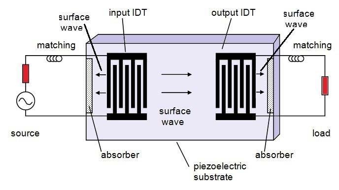
Figure 6: Diagram for a simple filter or delay line. Components shaded in red are the source and load impedances of the system. 50Ω system impedance is typical for most SAW applications. (Courtesy of D.P. Morgan, Wiley Handbook of RF/Microwave Components and Engineering, Ch. 6, 1-13-2003, p 3)
3. Triple Transit and Other Time Spurious
Triple transit signals are the result of the SAW waves being regenerated from reflections off the output transducer and launched back towards the input transducer for a subsequent regeneration per Figure 7. For a conventional SAW, triple transit (TT) is related to
the insertion loss (IL) approximately by:
TT = (IL * 2) + 6 dB
For example, a conventional SAW with 6 dB of loss would have an ideal triple transit of (6*2) + 6 ~18 dB. Hence, for each additional 1 dB of insertion loss, the triple transit reduces by approximately 2 dB.
Feedthrough is an unwanted direct leakage signal that is present at time t~0 that leads the main processed signal through the SAW filter or delay line (also termed ‘zero time spurious’).
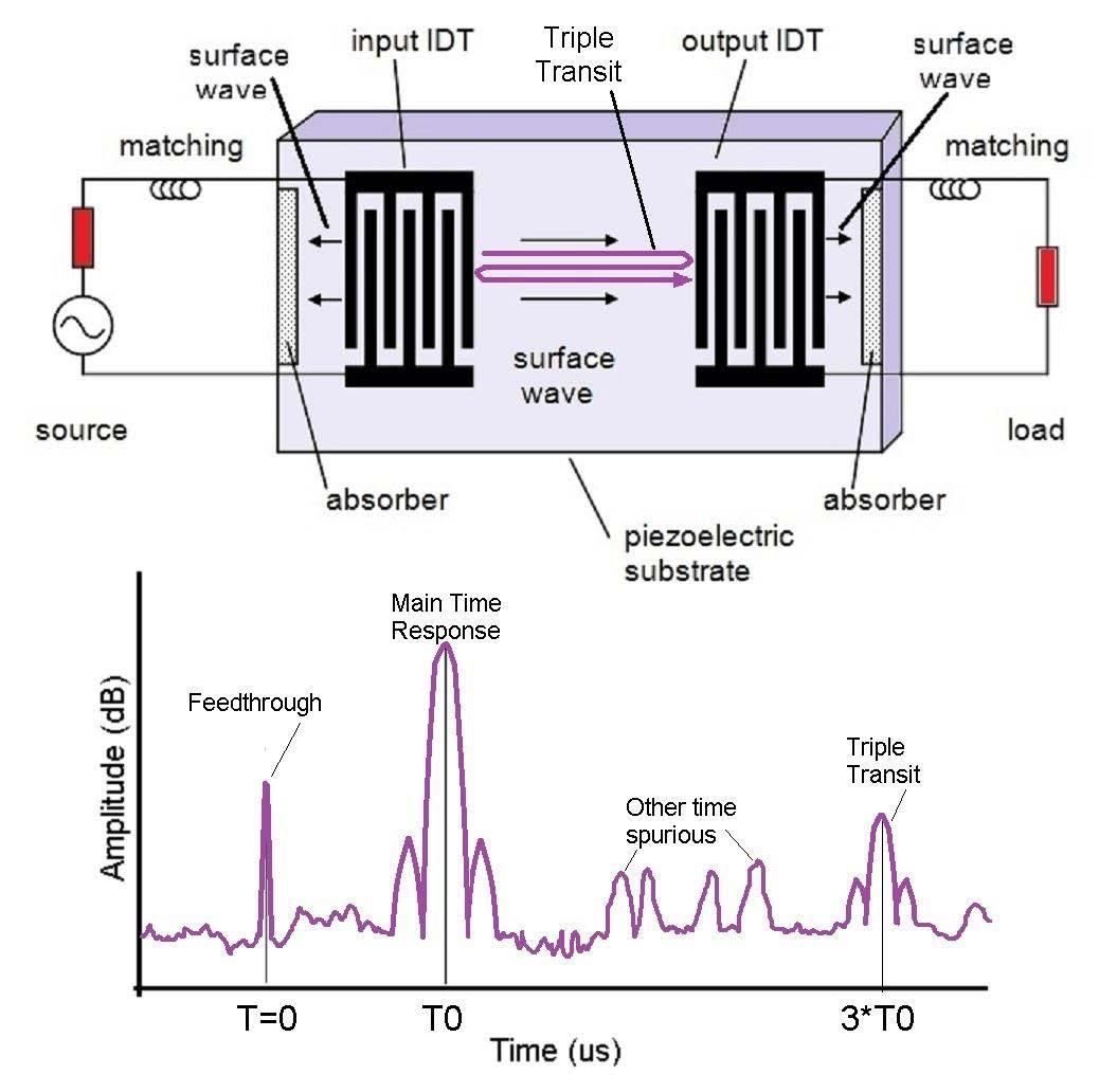
Figure 7: Triple Transit Response: The generated wave is reflected back then regenerated as a second wave. The signal will show up at 3 times the nominal device delay (T0) in the time response. Waves generated in the -X direction may also appear as unwanted spurious in time.
Also, not all of the converted energy from the transducer will travel along the surface of the piezoelectric substrate. Some will travel into the crystal itself as BAW (bulk acoustic waves). These modes will show up in the processed filter response as shown in Figures 8 and 9.
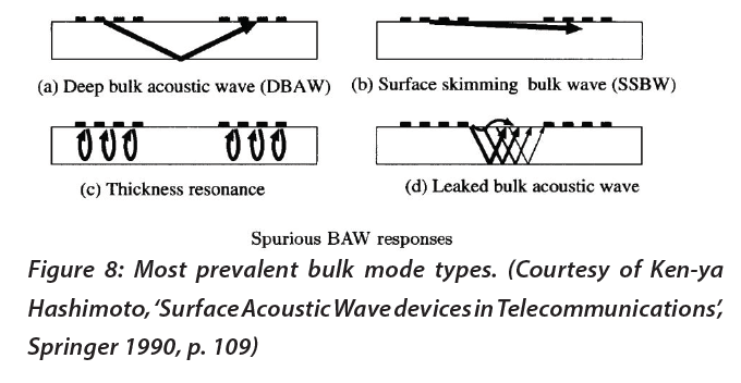
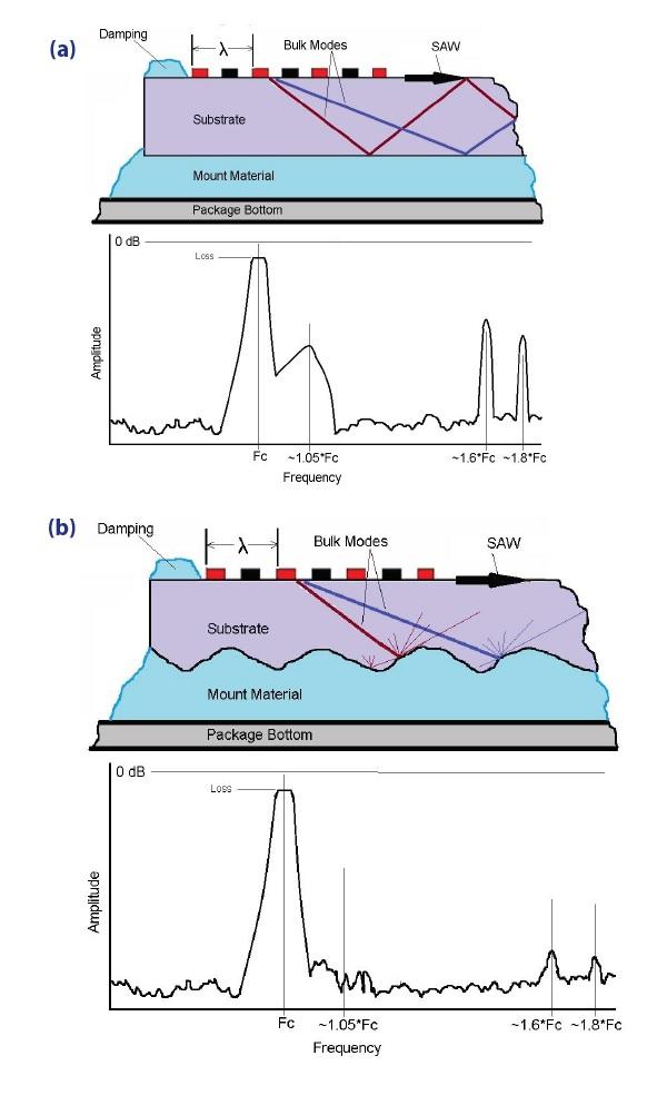
Figure 9:
(a) Bulk Modes in a quartz SAW crystal (side view).
(b) Several proprietary techniques at Spectrum Control help to eliminate most bulk modes, reducing their effect on the overall filter response (with aid from ‘Surface-Wave Devices for Signal Processing’, by David P. Morgan,
Elsevier 1991, p. 64-67).
4. Low Loss SAW Filters
For many applications, a lower loss, and smaller size will be required in situations where standard filter performance may be inadequate. Several design techniques are available to help meet requirements that cannot be met with conventional SAW technology.
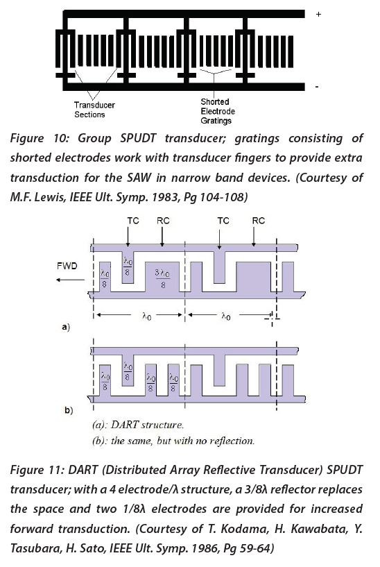
SPUDT (Single Phase Unidirectional Transducer) filters: Reducing amplitude of the SAW in the -X direction and increasing the SAW in the +X direction by utilizing reflector electrodes within the transducer(s).
 -
-
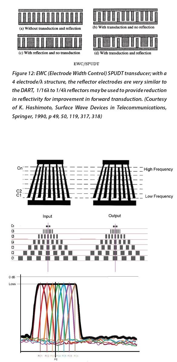
Figures 10, 11, and 12 provide exceptional narrowband low-loss filters but do not work as well if a wideband low loss device is required. To provide for the wideband versions of these filter types, a fan transducer (a.k.a. slanted or tapered) is employed to create the wider
bandwidth and lower loss that isn’t possible with a bi-directional design.
Analysis of the fan transducer is performed by ‘cutting the transducer into horizontal strips’ or by channelizing; each channel represents a narrowband low loss filter in of itself at each frequency region as the wavelength changes along the height (aperture) of the electrode
patterns. Each of these channels (C1, C2, C3, Cn) is analyzed then they are recombined to form the full filter response as shown in Figure 13.
Figure 13: Pair of FAN Transducers with 4 electrode/λ structure. Low loss techniques can be incorporated and analyzed by using channelization. The result for each channel is electrically combined to produce an overall response with a much wider bandwidth. The advantages of the low loss design are retained in the overall filter (Courtesy Spectrum Control)
Figures 14 and 15 demonstrate other methods to produce a low loss device, but these are very limited in use.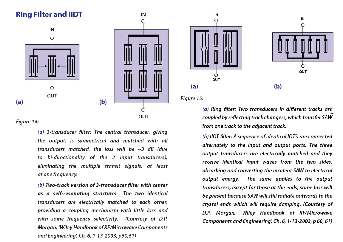
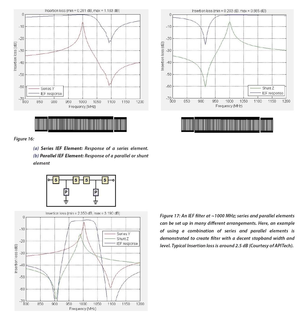
Resonator Filter: IEF (Impedance Element Filter):
The IEF is well-suited for large bandwidths, higher center frequencies and for very small size. Also, due to the materials used (42º Tantalate, 41º Niobate), greater input power may be applied since the SAW travels through a larger portion of the substrate material. The IEF filter is designed with parallel and series elements (Figure 16) arranged and modified accordingly to achieve a desired filter shape by taking advantage of the resonance characteristics of each element type (Figure 17).
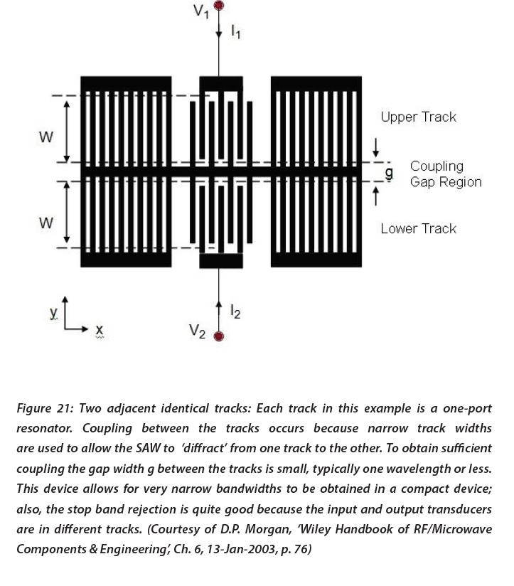
CRF and TCRF (Coupled Resonator Filters)
Coupled resonator filters (CRF) can be designed with both wide or narrow bandwidths and low loss for many different applications. CRF filters are based upon the single pole and two pole configurations shown in Figures 18 and 19.
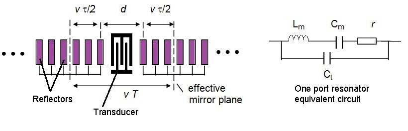
Figure 18: The one port resonator: A central transducer in combination with symmetric reflector gratings is designed to resonate at a specific Fc. The response is sensitive to the cavity length (in time units of T). Equivalent circuit for the one port resonator is included. (Courtesy of D.P. Morgan, ‘Wiley Handbook of RF/Microwave Components & Engineering’,
Ch. 6, 13-Jan-2003, pp. 71, 72)
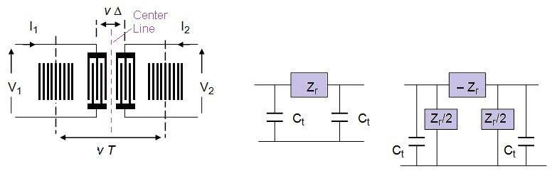
Figure 19: The two port resonator:
(a) two non-reflective transducers are assumed to be identical and symmetric. The entire resonator is also set up to be symmetric about its center. The cavity length (in time units) is T (same as in the one port resonator) and the distance between transducer centers is vΔ.
(b) and (c) are equivalent circuits for the anti-symmetric and symmetric modes. (Courtesy of D.P. Morgan, ‘Wiley Handbook of RF/Microwave Components & Engineering’, Ch. 6, 13-Jan-2003, p. 73; Ken-ya Hashimoto, ‘Surface Acoustic Wave devices in Telecommunications’, Springer 1990, p. 145).
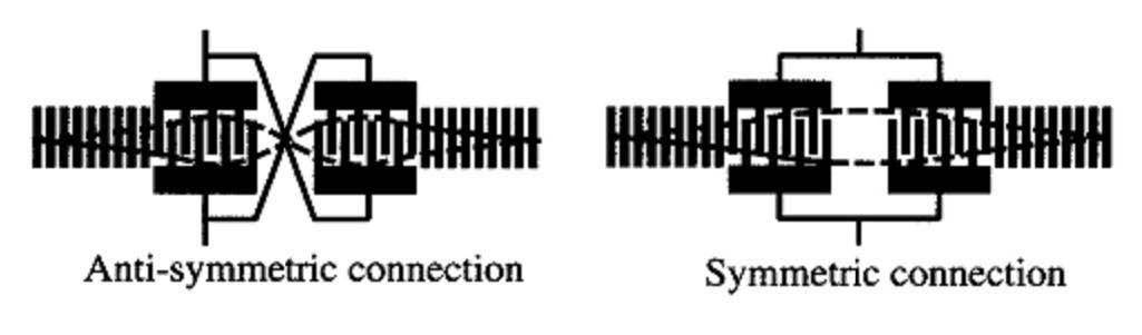
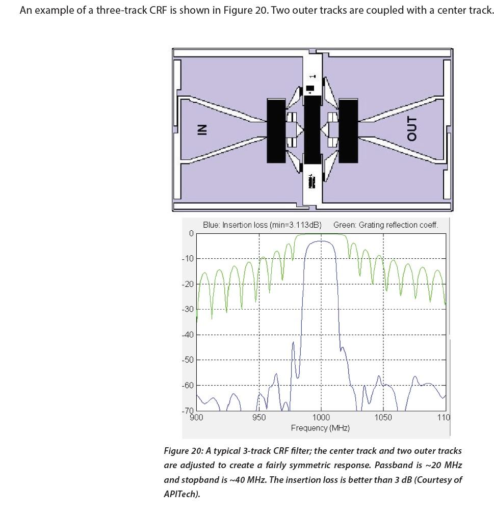
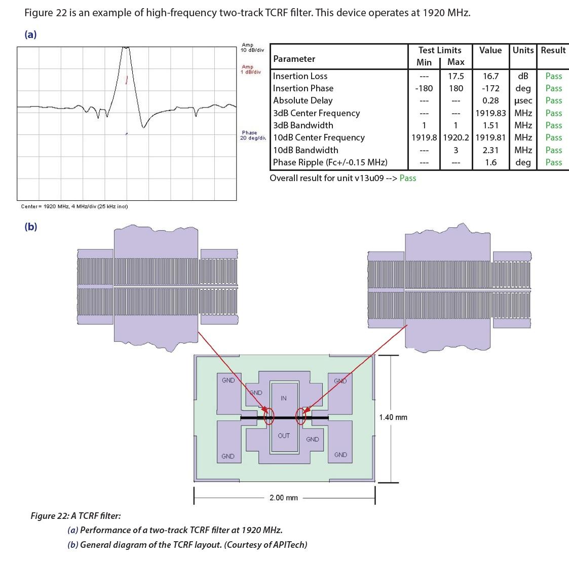
The TCRF filter (Transverse-coupled Resonator Filter) consists of resonators similar to those shown in Figure 18 and 19 connected electrically to form a narrow band filter. Filters using two or more resonators are configured so that the resonators are acoustically coupled transversally within the device.
Analysis of the TCRF is comprised of resonance (the resonator elements themselves) and waveguide (area where the two adjacent resonators are transversally coupled) components. Fortunately, these two elements may be analyzed separately. The waveguide portion is isolated from the resonance and analyzed then the analysis of the resonance is
performed and added afterwards.
Application for SAW Products
1. Communications
SAW filters provide bandpass filtering in many military communications applications, including Rx and Tx filters, IF filters in superheterodyne systems and IF filters within Software Defined Radio (SDR) applications, and Identification Friend or Foe (IFF) applications. SAW filters can be produced to provide high selectivity and low distortion with smaller sizes and lower costs than many other alternate filter technologies.
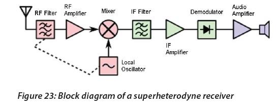
A block diagram for a superheterodyne receiver is shown in Figure 23. The RF bandpass filter and IF bandpass filter selection is often chosen with SAW technology to provide suppression of the transmission leakage and other interference in the RF stage and high selectivity SAW filters are used in the IF stage for channel filtering.
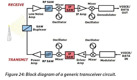
SAW filters are also used in transceiver systems as shown in Figure 24. SAW technology may also be employed in the duplexer and could be utilized for local oscillators.
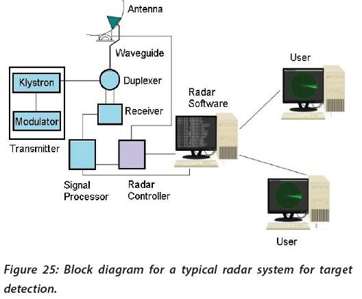
2. Radar
Another branch of SAW technology, used extensively in radar applications, involves the utilization of filters that possess a linear delay change over a set pass band width, also termed TB or time bandwidth product. The larger the TB, the better the system will be at locating and tracking a target. Combined with digital signal processing, a SAW based system is extremely adept at tracking a target. A typical system is shown in Figure 28. Dispersive SAW delay lines and filters reside in the transmitter and receiver within a single system to perform both pulse compression and expansion.
The pulse compression radar has dispersive or ‘chirp’ filters in both the transmit and receive sections of the system. The function of these filters is to either compress or expand the radar signal on the transmit and receive sections, respectively. This provides the means to reduce the power of the radar transmit signal with shorter duration. The sensitivity of the radar is maintained with the increased signal to noise ratio.
The latest military radar systems being employed are the AESA (active electronically scanned array) type. The AESA is a phased array antenna that steers radio waves to point
in different directions without moving the antenna itself. Each antenna element is connected to a small module which is able to perform both transmitter and receiver functions for the antenna through computer control.
The AESA radar can send out multiple beams of radio waves at multiple frequencies simultaneously and can spread their signal emissions across a wider range of frequencies, which makes them more difficult to detect over background noise. This allows ships and aircraft to emit powerful radar signals while still remaining stealth. The opportunity for the use of SAW product in this field is substantial.
3. Telecommunications
SAW filters are well suited for telecommunications due to their small size, weight and durability Resonator filters described above provide the electrical characteristics desired for Tx and Rx filters, such as low loss and superior passband and stopband performance.
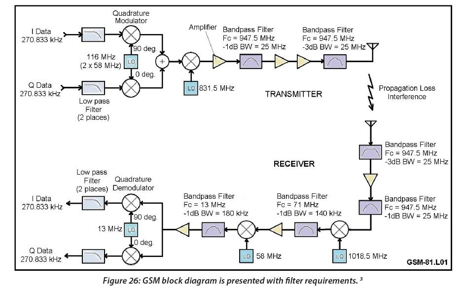
SAW filters are the most common filter construction for mobile devices. They can be incorporated as transmit, receive and duplex configurations, where both transmit and receive paths are in a single channel. SAW products are predominantly used up to 2 GHz.SAW filters are ideal for GSM (global system for mobile communications), CDMA (code division multiple access), WCDMA (wideband CDMA) and LTE (long-term evolution) bands, Figure 26.
Filters are also required for base station applications in telecommunications. SAW filters may be implemented as bandpass filters in the IF stage. These filters ideally have low distortion and minimal passband amplitude variation.
4. Medical Applications
SAW products may be used in many applications within the medical field. Some typical applications are communications, signal processing and as sensors.
One of the more practical applications is to use SAW filters as bandpass filters for the transmit and receive sections of wireless communication. The specific applications would be similar to the sections above, but utilizing specific bands, such as the ISM frequency bands. These are typically low power, near field communications.
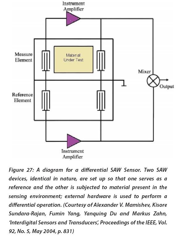
SAW products used for sensors are another application in the medical field. A unique application is to use a SAW delay line as a sensor element for in-situ detection of a wide array of stimuli per Figure 27. Typically, a selective film is applied to the SAW delay line to enable precise detection and quantification of the specific element.
Download Introduction to Saw Filter Design