EMI Filter Installation Guidelines
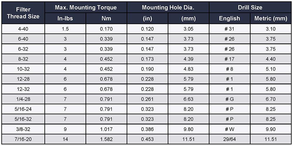
Threaded Style EMI Filters
-
Exceeding recommended mounting torque may cause damage to the capacitor within the filter because of possible twisting or elongation of the case.
-
For products without hex surfaces, do not hold the filter with pliers or other gripping tools. Pressure exerted on the filter case may crack the ceramic capacitor element.
-
Proper use of filters requires that the filter case be adequately grounded to form an effective path for the interference.
Solder-in Style EMI Filters
-
A controlled temperature profile not exceeding 6°F (3°C) per second is recommended when soldering filters.
-
When soldering to terminals of a filter, a heat sink should always be used adjacent to the body of the filter.
-
60-40 solder is recommended for installation of the filter into the chassis and soldering to the terminals. If a filter style without an eyelet is being soldered into a chassis, iron processes should be avoided and the recommended solder alloy is 60-38-2.
-
Installation hole size for a solder-in filter should be 0.003-0.005” over the maximum tolerance of the minor diameter of the mounting portion of the eyelet with a ±0.002” tolerance.
-
Machine/oven soldering 385-415°F (195-210°C) using a dwell and cycle time fast enough to reflow the solder and ramped to maintain less than 6°F/sec rate of change.
- For iron soldering to filter body, preheat components at 250-300°F (120-150°C), solder iron is recommended to be set at 500-550°F (260-290°C). The dwell on the solder joint should be less than 5 seconds. The time depends on the heat sinking provided by the chassis, so a longer preheat may be required.
Soldering to EMI Filter Terminals
-
Use a temperature controlled soldering iron with tip temperature of 525 ± 10°F (275 ± 5°C).
-
Use an SN 63 RMA flux core solder.
-
Make mechanical wire connection.
-
Use heat sink next to filter body where possible.
-
Clean soldering iron tip.
-
Clip end of solder (remove 0.5”) to expose flux for soldering.
-
Apply soldering iron to wire/flag junction at wetted solder tip region of iron (Wetted Bridge Method). Immediately apply solder. Dwell time for soldering iron tip on product should be 3-5 seconds maximum.