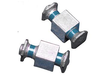
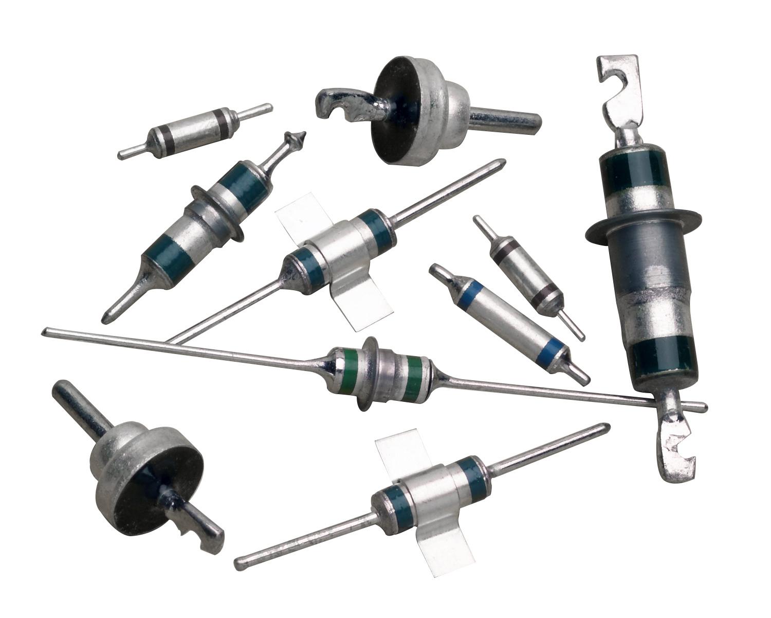
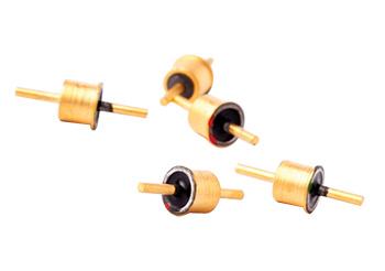
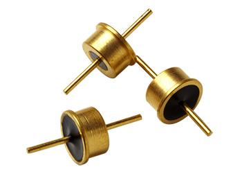
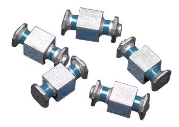
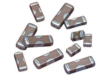
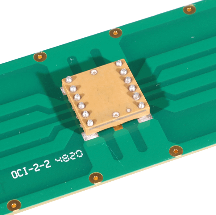
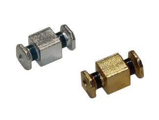
Switch-mode power supply (SMPS) capacitors are designed to provide superior
performance in high-frequency switching applications. SMPS capacitors are ideal for high energy density products found in both military and commercial markets. Spectrum Control's ceramic capacitors are designed and produced in the USA.
Spectrum Control can design products in accordance with DSCC 87106 and MIL-PRF-49470 standards. Visit Military Standard Qualified EMI Filters to see the cross-reference lists.
Style | Size | Dimensions | |||||
---|---|---|---|---|---|---|---|
A max |
B max |
C ±0.025” |
D ±0.025” |
E max |
Leads/ Sides |
||
SMP-3 | (in) | 0.650 | 0.715 | 0.450 | 1.050 | 0.500 | 10 |
(mm) | 16.50 | 18.16 | 11.42 | 26.65 | 12.69 | ||
SMP-4 | (in) | 0.650 | 0.715 | 0.400 | 0.400 | 0.440 | 4 |
(mm) | 16.50 | 18.16 | 10.15 | 10.15 | 11.17 | ||
SMP-5 | (in) | 0.650 | 0.715 | 0.250 | 0.250 | 0.300 | 3 |
Absolute Maximum Output Capacitance
|
Impedance vs. Frequency![]() |
ESR vs. Frequency![]() |
Absolute Maximum Capacitance ESR
|
Absolute Maximum Capacitance ESL
|
Test Group | Test Order |
Test | Test Method | Post Test Requirements | Sampling Procedure |
---|---|---|---|---|---|
Group A | 1 | Visual and Mechanical | 13 Samples 0 Failures |
||
2 | Materials, Designs, Construction and Workmanship | ||||
3 | Physical Dimensions and Marking |
||||
4 | Capacitance and Dissipation Factor | MIL-STD-202 Method 305 | 100% | ||
5 | Dielectric Withstanding Voltage | MIL-STD-202 Method 301, 2.5x DCWV except 500V @ 1.5x |
|||
6 | Insulation Resistance | MIL-STD-202 Method 302 @ DCWV, 25 C |
>100,000 megohms or 1,000 megohm-µF, whichever is less | ||
Group B Sub Group I |
1 | Voltage & Temperature Limits | 12 Samples 1 Failure |
||
2 | Resistance to Solvents | MIL-STD-202 Method 215 | |||
3 | Immersion | MIL-STD-202 Method 104 test condition B |
No mechanical damage. Dielectric strength, capacitance, df and 25 C IR to original limits |
||
4 | Terminal Strength | MIL-STD-202 Method 211 test condition A. Case codes 1-4, 6-5 lbs case code 5-4 lbs | No evidence of loosening or rupturing of terminals |
||
Group B Sub Group II |
1 | Resistance to Soldering Heat |
MIL-STD-202 Method 210 N lead style test condition B, J and L styles test condition I | No mechanical damage. Dielectric strength, capacitance, df and 25 C IR to original limits |
12 Samples 1 Failure |
2 | Moisture Resistance | MIL-STD-202 Method 106, 20 cycles |
No mechanical damage. Dielectric strength, capacitance, df and 25 C IR to original limits |
||
Group B Sub Group III |
1 | Life | MIL-STD-202 Method 108, 1000 hrs. 2x DCWV except 1.2x 500 DCWV | No mechanical damage. Dielectric strength, capacitance, df, 125 C IR and 25 C IR to original limits |
12 Samples 1 Failure |
Optional | Solderabililty Group A | ||||
Thermal Shock and Voltage Conditioning | |||||
Ultrasonic Examination | |||||
Destructive Physical Analysis | |||||
Shock, Specified Pulse | |||||
Vibration, High Frequency | |||||
Humidity, Steady State – Low Voltage | |||||
Barometric Pressure |