Power EMI Filter Application & Measurement Guidelines
Power EMI Filter Application & Measurement Guidelines
Need to limit Electromagnetic Interference
Global regulations limit electromagnetic interference from electronic devices that can easily disrupt wireless radio communications. These regulations have become increasingly important with the proliferation of portable and wireless electronic devices.
Electromagnetic Interference travels through wires and wirelessly
Conducted EMI travels through wires, such as power lines and data cables. Radiated EMI travels wirelessly through air and space. Please note that any wire that has conducted EMI will produce radiated EMI.
Interference types
The two types of conducted emissions are differential mode (symmetrical or normal mode) and common mode (asymmetrical mode). Differential mode EMI currents flow from one wire and return on another wire, so the currents flow differentially between the wires. Common mode EMI currents flow the same direction through one or more wires and return on the chassis ground, so the currents flow commonly through the wires.
Sources of EMI
Electromagnetic interference occurs naturally and from man-made devices. Natural sources of EMI include lightning, solar flares, sand and dust storms, and cosmic noise. Man-made sources include power lines, electric motors, power supplies, digital devices, and radio transmitters.
EMI filters, attenuation and insertion loss
EMI filters are used to attenuate, or decrease, the EMI from natural and man-made sources. Low-pass EMI filters use inductive and capacitive components to allow the lower frequency intended signals to pass through, while filtering out the higher frequency EMI.
APITech verifies the amount of attenuation provided by its filters through insertion loss testing. MIL-STD-220 details the methods of measuring the insertion loss of EMI filters using coaxial 50-ohm sources and measurement receivers typically from 10kHz to 10GHz. Reference readings taken through coaxial cables are compared to the readings obtained after the filter under test has been “inserted” into the measurement path, and the measured difference is the insertion loss of the filter expressed in dB. Custom insertion loss test systems designed and built in-house by APITech allow accurate and repeatable test results as required by today’s demanding applications. Custom fixturing simulates the end application and ensures compliance with insertion loss requirements.
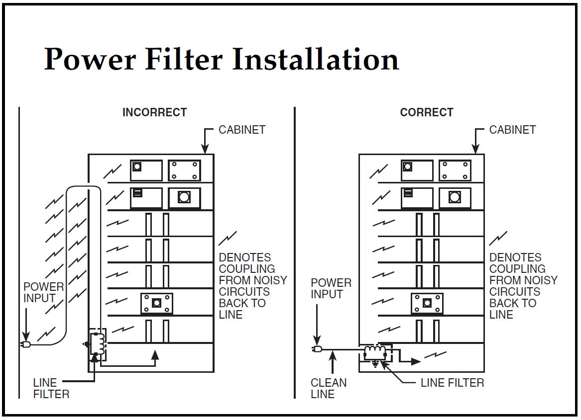
Installation Criteria
Proper installation of an EMI filter is critical to achieving successful filtering of electromagnetic interference. APITech recommends that EMI filters be installed at the point-of-entry to the chassis. The metallic chassis provides the shielding needed to isolate the filter’s input wires from the output wires. It is also critically important to provide a low-impedance bond between the filter and the equipment chassis to achieve the required insertion loss performance from the filter.
Differential (Normal or Symmetrical) Mode Insertion Loss
The most prevalent type of differential mode EMI is caused by the non-sinusoidal current flow from power supply rectifiers and other switching devices, which creates harmonic distortion. This EMI exists from the fundamental power frequency up to approximately 10 MHz. APITech measures differential mode insertion loss in a 50-ohm system with balun transformers as shown.

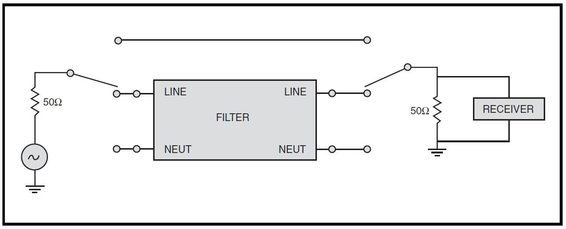
Common (Asymmetrical) Mode Insertion Loss
Common mode insertion loss is critical for all commercial, aviation, and military applications. In many ways it is the most common type of EMI. APITech measures common mode insertion loss on each line in a 50-ohm system as shown.
Leakage Current
Leakage current measures the amount of reactive current that flows from the filter through the system ground. It represents a potential shock hazard to personnel should there be an open in the ground connection. APITech uses the following test setup for leakage current measurement.

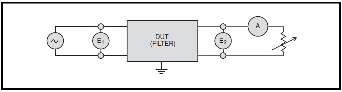
AC Voltage Drop
AC voltage drop is performed on a pair of lines together and is defined as E1 – E2 = AC voltage drop APITech uses the following circuit for AC voltage drop testing:
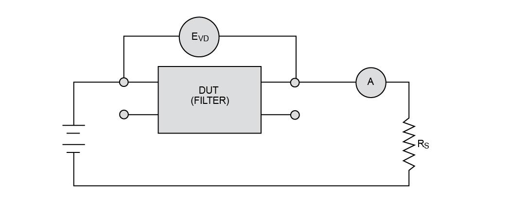
DC Voltage Drop
DC voltage drop is performed on each line individually. APITech uses the following circuit for DC voltage drop testing: